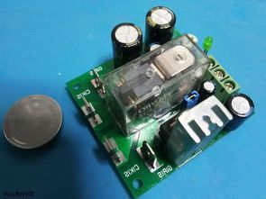
Speaker Protection Circuit
One of the reasons why the speakers fail is that the amplifier fails and gives DC voltage to the output. The speaker protection circuit detects the DC voltage at the..
Analog electronic Analog electronic projects application schematics
One of the reasons why the speakers fail is that the amplifier fails and gives DC voltage to the output. The speaker protection circuit detects the DC voltage at the..
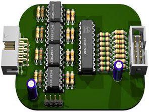
Galvanic isolation for a logic analyzer with 8 channels. Galvanic isolation for Logic Analyzer with 8 channels. Suitable for use up to 2MBit with 2V level and a little faster..
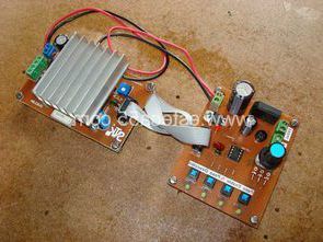
The purpose of the Motor Driver Test card is to check any of the motor drivers used especially in CNC machines. The tester is connected directly to the motor driver..
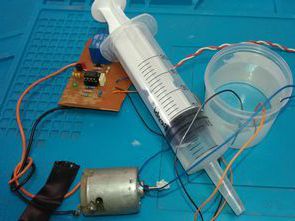
Simple 555 circuit. The water tank filling circuit is based on the NE555 timer IC. By measuring the water level in the tank, it automatically starts the water pump motor..
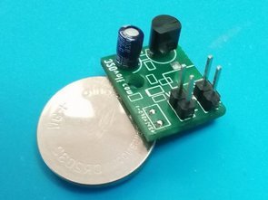
A circuit PCB design that adjusts the fan speed according to the temperature was made as small as possible, most of the components are SMD, in addition to the fan..
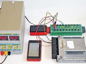
The project is an external OBDII socket interface that allows easy access to the CAN bus and other transmission lines used by vehicle manufacturers using a diagnostic tester. Recommendations: the..
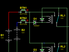
Simple circuit with relay that directs output at the correct polarity when DC input is reversed. In reverse polarity protection, there is no output in the wrong connection. With this..
An uncomplicated layout that will perfectly test sift wherever necessary delay the application of any device. Delay time it can be adjusted from about 2 to 120 seconds. It may..
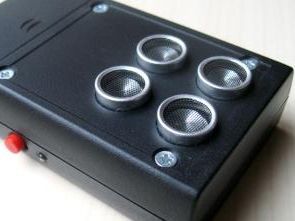
There are alternatives on the market with 4 TR2516T1 ultrasonic transmitter plow transmitter 25kHz 16mm dimensions, the output of which is installed on the CD4093A integrated circuit of the ultrasonic..
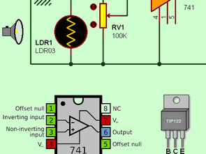
The circuit diagram you see in the picture works as a dark switch with the LDR on it. The circuit consists of four resistors, a 741 opamp, two potentiometers (optional..