Galvanic isolation for a logic analyzer with 8 channels. Galvanic isolation for Logic Analyzer with 8 channels. Suitable for use up to 2MBit with 2V level and a little faster at higher levels. As always, everything is freely available, including a circuit diagram, board, etching mask and even a Reichelt shopping basket.
I have purchased an evaluation kit which can be converted into a very good logic analyzer with Sigrok. However, there is no galvanic isolation there. Therefore I designed a suitable adapter with galvanic isolation, which can also be transferred to other logic analyzers. The box galvanically separates 8 channels of the Logic Analyzer from the device to be examined (DUT).
The box is supplied by the logic analyzer, so this should provide 5V or an external 5V supply should be connected. My logic analyzer uses a 10-pin socket on which 8 channels and two GND pins are available in the original. I disconnected a GND pin and applied 5V (then 4.8V) from the USB connection via a Schottky diode. The assignment now matches the Atmel AVR kits. Pin 1-8 are channel 0-7 of the logic analyzer, pin9 is GND and pin10 is 4.8V. If you cannot lead out 5V on your analyzer, you can rewire the DC / DC converter and thus obtain 5V from the device to be tested.
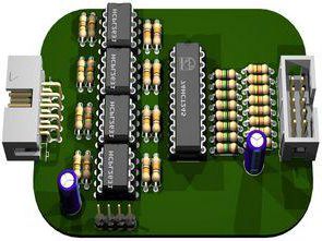
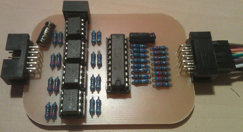
The supply of the box is necessary because Hi-Speed optocouplers (HCPL 2631, 10MBit) are used there. A 74HCT245 serves as the input impedance converter. A DC / DC converter is used to separate the supply voltage from the input and output side. The TME 0505S can easily be replaced by a SIM1-0505 SIL4. A Reichelt shopping cart WITHOUT PCB AND IC SOCKET is prepared.
Features:
Separation of the target from the logic analyzer. Compared to USB isolators, the logic analyzer itself is also protected.
Galvanically separated supply of the target device possible (4.8V..5V, max 100mA).
8 galvanically separated channels
! not separated from each other by channel, but compared to the PC / analyzer!
10MBit transmission possible (up to 2MBit @ 2V and 5MBit @ 5V recommended)
Easy replacement of defective components as there are no SMDs.
! Only if all ICs and DC / DC converters are socketed!
Sensitive switching threshold (according to data sheet 2V, also more sensitive in the test at room temperature)
I avoid making statements about the insulation voltage of the finished device, as this depends a lot on the layout and the quality of the etching or milling process of the board. I also recommend the use of an insulating protective varnish (e.g. contact chemistry “plastic”).
So much can be said: According to the data sheet, the DC / DC converter is designed up to 1kV (DC) and the HCPL2631 up to 2.5kV (Vrms).
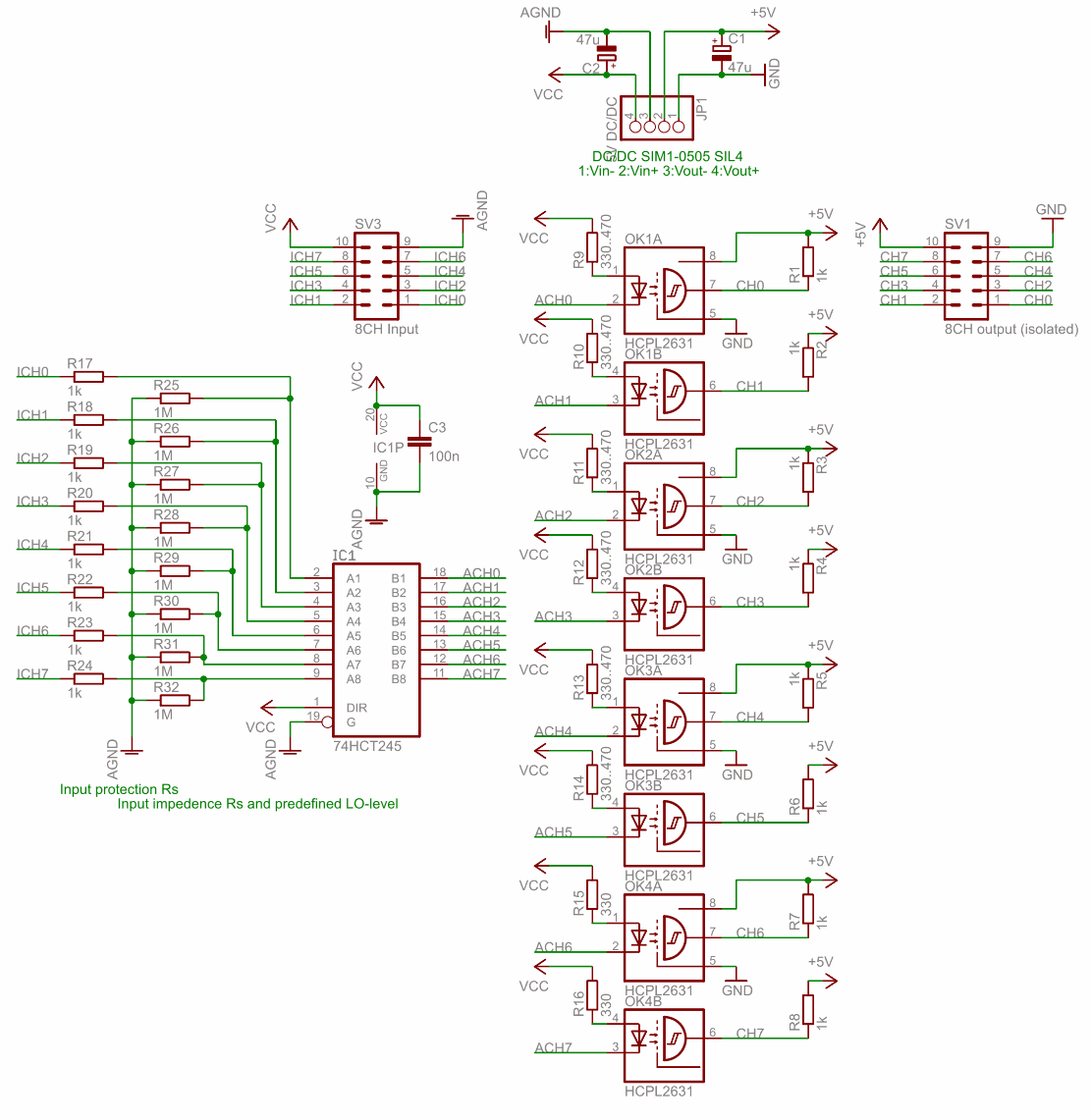
Galvanic Isolation Circuit Diagram
Tests on the signal generator in connection with an oscilloscope show suitability up to 1.6V and 2MBit and 5MBit at 3V level. Signals up to 10Mbit get through without any problems, but can no longer be properly assessed due to the dragging of the signal edges. Then a strong attenuation sets in at the output, but 20MHz at the input are also mapped with 20MHz at the output. I couldn’t test over 20Mhz because my signal generator isn’t faster.
Digital interfaces with 2MBit and 1.6V level and even 5MBit interfaces with 3V level can be examined in a meaningful way, however, at 8MBit the first problems occur and from 10MHz the device is only of limited use for practical use, as a square wave signal with 50% duty cycle with the correct frequency but with a strongly falsified duty cycle. However, according to the manufacturer, the HCPL2361 is only suitable up to 10MBit.
My Logic Analyzer can only handle a maximum sampling rate of 24MHz anyway. Therefore this is practically no restriction in connection with my device. But if you use it on another logic analyzer, you should take this into account. In addition, these are values from a practical test with my components at room temperature -> temperature fluctuations and component tolerances are not taken into account!
FILE DOWNLOAD LINK LIST (in TXT format or file): 27844a.rar pass: 320volt.com
Source: keinschnickschnack.de/?p=737


