2kVA, 4kVA PFC-supported Amplifier SMPS circuits. The SMPS PWM stage is controlled with SG3525, and the high voltage PFC stage is controlled with NCP1653A. It has a symmetrical +- 90 volt output. The main reason switching power supplies are preferred instead of classic linear power supplies in high-power amplifier projects is that they provide lower weight, higher efficiency, and a compact structure.
2000W SMPS 90V 15A Half Bridge PFC Circuit (IR2110, SG3525A, NCP1653A)
Contents
- 1 2000W SMPS 90V 15A Half Bridge PFC Circuit (IR2110, SG3525A, NCP1653A)
- 2 General Structure of the Circuit
- 3 PFC Stage and NCP1653A IC
- 4 Half Bridge Drive Structure with SG3525A and IR2110
- 5 Auxiliary Power Supply and UC3845 Section
- 6 EMI Filter, Soft Start, and Protection Details
- 7 Transformer Core and Primary Winding Information
- 8 Winding Wire Thickness Issue
- 9 Trimpot Adjustments
- 10 SMPS and PFC Protection System
- 11 4000W SMPS Full Bridge PFC Circuit and Schematic (IR2110, SG3525A, NCP1653A)
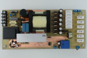
A SMPS design with a Half Bridge (HB) topology, an active PFC stage at the input, and approximately 2kVA power.
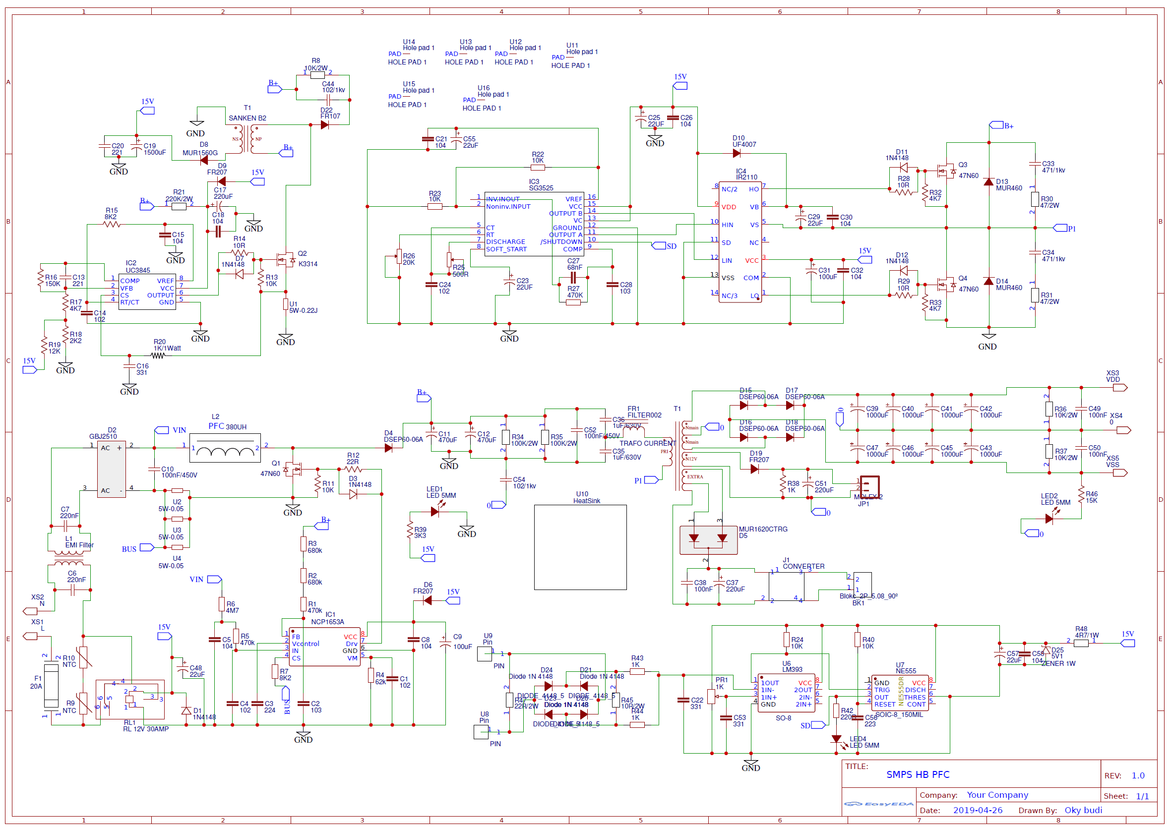
2000W SMPS Circuit Schematic;
General Structure of the Circuit
This SMPS design basically consists of four main sections:
- Input rectification and EMI filter section
- NCP1653A PFC boost stage
- SG3525A + IR2110 based Half Bridge PWM power section
- Auxiliary power supply section created with UC3845
With this structure, the aim is not only to generate high power, but also to draw the input current in a more controlled way and drive the main power stage more stably.
PFC Stage and NCP1653A IC
In the project, NCP1653A is used in the PFC stage. This IC is designed for boost converter control for active power factor correction (PFC). It helps shape the input current more properly and is of great importance in high-power SMPS designs.
According to the information shared for the PFC coil, 1 turn / 1.5 mm copper wire was used on a toroidal ferrite core. The given core dimensions are as follows:
- Outer diameter: 47 mm
- Inner diameter: 24 mm
- Thickness: 18 mm

Half Bridge Drive Structure with SG3525A and IR2110
The main PWM generation is provided with SG3525A. SG3525A frequency adjustment is still one of the control ICs frequently used in classic SMPS designs due to its duty control, soft-start, and protection functions.
The high-side and low-side MOSFET drive process is carried out with IR2110. This IC is a suitable gate driver for driving high-side and low-side N-channel MOSFETs in a Half Bridge structure. In this way, the PWM signal coming from the SG3525A is not given directly to the power MOSFETs, but is driven more strongly and safely.
The gate signal measured in the circuit appears to be approximately 82 kHz frequency and %38.1 duty cycle.

Auxiliary Power Supply and UC3845 Section
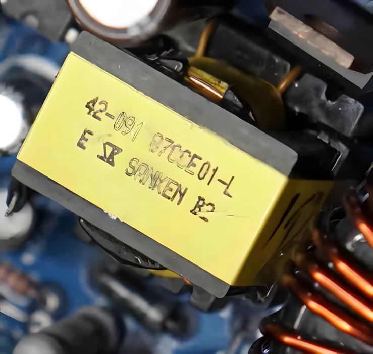
In the SMPS design, a separate small power supply is used for the auxiliary PWM supply. In this section, UC3845 was preferred. The auxiliary power supply stage helps the main control section operate with a more regulated supply without being directly dependent on the high voltage line, but there is no winding information for the transformer used with UC3845; a ready-made SANKEN B2 transformer was used.
EMI Filter, Soft Start, and Protection Details
On the input filter side, the use of approximately 3.5 mH EMI filter is recommended. On the 230V inrush current limiting (soft start) side, a resistor in the 47-100 ohm / 5W range is used instead of an NTC.
This section should not be neglected in high-power SMPS designs. These parts play a critical role especially in terms of the current surge at the first energizing moment, EMI behavior, and protection of the power components.


Transformer Core and Primary Winding Information
It is stated that an EE55/28/21 ferrite core was used for the main power transformer. The shared primary turn counts according to the operating frequency are as follows:
- 30-40 kHz = 18 turns
- 40-50 kHz = 16 turns
- 50-60 kHz = 15 turns
- 60-80 kHz = 14 turns
- 80-100 kHz = 12 turns
- 100-130 kHz = 10 turns
According to the given example, a symmetrical 90V output is targeted with Np = 14 turns and Ns = 6 + 6 turns.

Winding Wire Thickness Issue
Important note: In the original post, the winding wire diameter or number of wires of the main EE55 power transformer was not clearly specified. Therefore, it would not be correct to give a definite wire thickness for the main transformer.
Since the wire diameter of the main EE55 power transformer was not specified in the original post, it would not be correct to give a definite value. However, in the approximate 80-100 kHz operating range, using multiple thin parallel wires instead of a single thick wire is more suitable.
As a starting point for this design, a total copper cross-section of approximately 2 mm² for 14 turns on the primary, for example 8 pieces of 0.50 mm parallel wire; and on the secondary, a total copper cross-section of approximately 2.5-3 mm² for each 6-turn arm, for example 12 pieces of 0.50 mm parallel wire, can be considered.
These values are not a strict rule, but a safe starting suggestion. In the first prototype, transformer temperature, MOSFET heating, and voltage drop under load must definitely be checked.
There is another critical note: If the transformer overheats more than necessary, the solution is not a thicker single wire. TI recommends much thinner individual strands for real litz wire around 100 kHz; in other words, 0.45–0.50 mm parallel wires are not theoretically ideal, but practical.
It is done in terms of hand winding and material availability, but if the transformer overheats, the solution is not “a thicker single wire”, but switching to a larger number of thinner parallel wires or foil.
In practice, the following path can be followed:
- First, the primary and secondary RMS currents are approximately calculated
- The total copper cross-section that will fit into the winding window is determined
- As the frequency increases, a multi-strand structure is preferred instead of a single thick wire
- In the first prototype, temperature and no-load current must definitely be measured
So here, the wire thickness should not be determined by guesswork, but with calculation + testing + temperature control.
Trimpot Adjustments
It is stated that there are four different adjustment points in the project:
- PWM frequency adjustment: 30-130 kHz
- Duty cycle adjustment: approximately %30-%40 range
- Overcurrent sensitivity adjustment
- Auxiliary DC output adjustment
These adjustments must be made with an oscilloscope and controlled load testing. Especially duty cycle and frequency adjustment directly affect MOSFET heating and transformer behavior.

SMPS and PFC Protection System
1) The PFC stage has its own current control / protection
On the lower left side, there is the boost PFC section built with NCP1653A + Q1 + L2 + D4. Here, it is clear that there is already a current monitoring / limit logic through the PFC control IC. So there is a separate protection on the PFC side.
2) Separate fault / shutdown circuit for the main SMPS
U8 / U9 pins, the 22R/2W burden resistor between them, then D21, D24 and other 1N4148 diodes, bridge rectification with R43 / PR1 / C22 / C53 for threshold and filtering, comparison with LM393, timing / latch / delay-like control with NE555, and the SD line at the output
In this chain, the AC signal coming from the current transformer is rectified → filtered → compared with the threshold → if a fault occurs, the shutdown process is triggered through the 555.
Anyway, it goes on and on. This structure was not used in the 2kW version, so do not take this section in the schematic into account. The shunt resistor and transistor structure in the 4kW SMPS schematic was used. Things have become a little mixed up. These are designs that can be used for inspiration even if they are not built…

4000W SMPS Full Bridge PFC Circuit and Schematic (IR2110, SG3525A, NCP1653A)
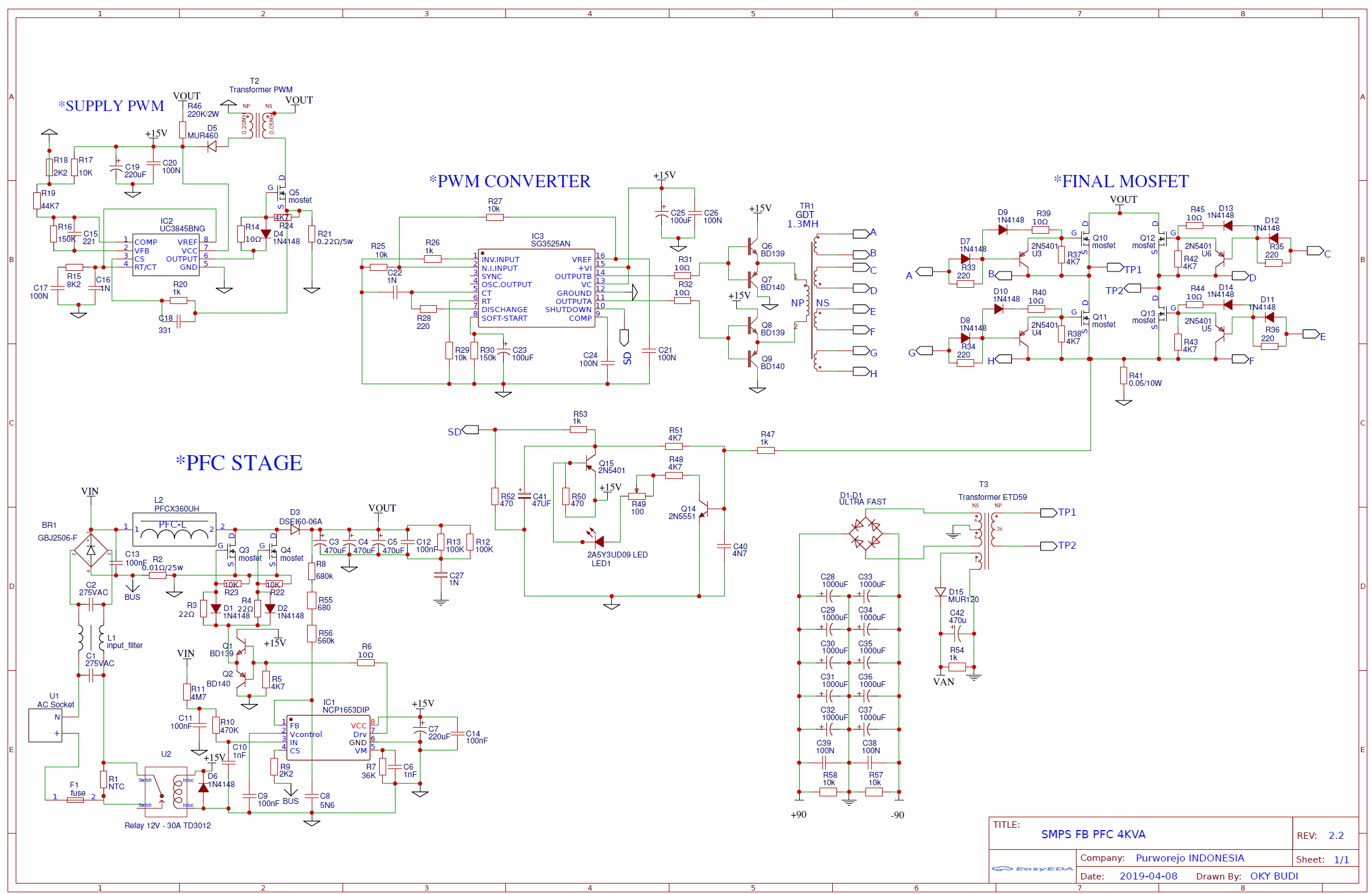
In the 4kW SMPS design, overcurrent protection is provided based on the principle of processing the current information taken from the shunt resistor in the MOSFET return line with a transistorized shutdown circuit. In the schematic, while R41 (0.05 ohm / 10W) acts as the shunt resistor, the voltage across this resistor is controlled with Q14 and Q15 transistors.
When the current threshold value is exceeded, the circuit triggers the SD (shutdown) line and stops the SG3525A control stage, thus putting the power section under protection.
In the 4kW version, the main overcurrent protection is built with a shunt resistor + transistorized shutdown structure. Here, the R41 (0.05Ω / 10W) shunt resistor located in the return line of the power MOSFETs senses the current. The voltage formed across this resistor goes to the filtering/signal shaping network around R47, R51, R48, C40, and is then processed by the Q14 (2N5551) and Q15 (2N5401) transistors.
When the current threshold value is exceeded, this circuit triggers the SD (shutdown) line and turns off the SG3525A driver. In other words, the protection does not work with LM393 + 555; it works with discrete transistor protection logic based directly on the information taken from the shunt resistor.
4kW SMPS Circuit Schematic
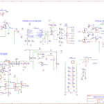
WARNING The 90V SMPS Circuit operates with high voltage. Be careful, pay attention to capacitor connections. If you connect the + – polarities in reverse, large explosions may occur at high voltage. Before operating the circuit, use a Fused Electrical Line and protective glasses.
Source: elcircuit.com (closed)