OpAmp Tester Circuit
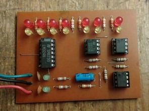
It is actually a simple circuit that makes a flip flop with three different opamp types. The PCB design of the elector is slightly different and the sockets used for..
Analog electronic Analog electronic projects application schematics
It is actually a simple circuit that makes a flip flop with three different opamp types. The PCB design of the elector is slightly different and the sockets used for..
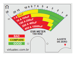
Classic analog ESR meter is a circuit based on SN74HC14N integrated circuit, it mainly consists of 150Khz oscillator, buffer, comparator and rectifier amplifier. The maximum range is approximately 75 Ohms..
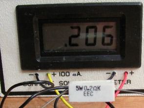
Simple Circuit for measuring low resistance values. It is designed to measure low resistance values from 0.01 to 19.99 Ohms. The measurement circuit and the voltmeter must be fed from..
When implementing control systems, you may encounter many problems of an analog-digital nature. One of these is to detect whether alternating current of a certain intensity passes through a particular..
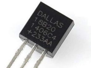
When the DS18B20 Temperature Sensor is transported over long distances, there is a danger of high voltage pulses being transmitted to the cable connecting the sensor to the control unit…
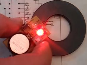
Magnet polarity detector. You can find out where the south or north of the magnet is by bringing another magnet of known polarity. And if the pole of a known..
With the rapid development of electronics, it is unfortunately becoming commonplace to install wireless devices for listening and video transmission in apartments and workplaces. However, even if the operating systems..
Temperature measurement is one of the more problematic in electronics. Digital output sensors have a very limited operating range and platinum ones are expensive. Inexpensive silicon sensors may be a..
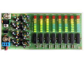
LM3915 The connection stands and falls with analog amplification and filtering of audio signals using operational amplifiers. The audio signal is first amplified and impedance separated by connection with the..
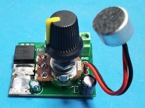
The microphone vu meter circuit was normally a classic design with 10, I just rearranged it as a single channel strip led vu meter by using the microphone preamp stage..