One of the reasons why the speakers fail is that the amplifier fails and gives DC voltage to the output. The speaker protection circuit detects the DC voltage at the amplifier output and disconnects the speaker. The DC voltage detection level of the protection circuit is very low (0.7…1V) so that the speaker is protected from being exposed to high voltage.
The loudspeaker protection circuit is connected to the outputs of 2×200 or 1x400w amplifier circuits with a double contact relay, and no adjustments are required on the usable amplifier.
The relay in the speaker protection circuit connects the amplifier output and the speakers with a delay according to the set time.
In addition, I added a thermal fuse connection to prevent malfunctions that may occur due to overheating of the amplifier. The thermal fuse mounted on the cooler of the amplifier cuts the voltage of the protection circuit at high temperature, the relay contacts leave the speaker amplifier circuit, the thermal fuse value can be 70…75 degrees. This feature is optional, you can directly short-circuit it and use it.
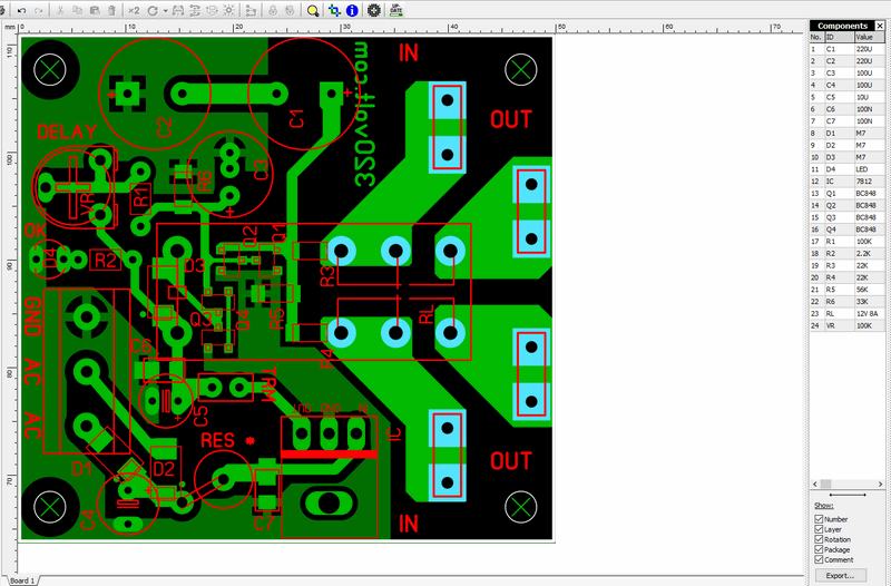
Speaker Protection Circuit Diagram


Greetings… with what negative voltage value does it shoot?
Hi, It shoots with positive voltage between 07…1v
Thanks for the answer, I’m going to try it, but for it to be an effective protection it must also trigger with negative tension because any of the 2 power rails can fail
It will work with negative because it takes ground from the zero line. try the circuit
Great circuit! Now with your permission I’ll design my own pcb (much bigger) because I don’t have a 8pin relay, so I’ll use two 5pin relays. Thank you very much.
Hi,
You’re welcome. Good work 👍
Hi Mr. gevv, how are you? I hope fine. Finally it´s done my dc loudspeaker protection board (320volt.com based). There is a pic12F683 for leds and relays controll. The DC detector is yours. Thank you very much. regards from Brazil.
https://ibb.co/tCGDbZr
https://ibb.co/Vx2MnZ4
https://ibb.co/b5sbZ4M
Hi, Thank you for feedback. Nice job
Hi
Can you please explain the purpose of every part in the circuit.? In other words. How dors it work?
What does P1 100K do?