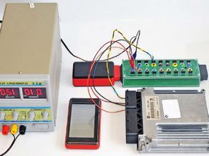
The project is an external OBDII socket interface that allows easy access to the CAN bus and other transmission lines used by vehicle manufacturers using a diagnostic tester. Recommendations: the project is designed for car services and workshops dealing with electronics and diagnostics.
All electronic modules are connected in parallel to a 2-wire twisted pair. The data in the twisted pair is transmitted by means of a differential signal, thanks to which the signal has increased resistance to external electromagnetic disturbances. To eliminate wave reflections at both ends of the bus, terminating resistors with a resistance of 120 V are used. It may be variable depending on the data transmission speed and the type of twisted pair used.
There are two wires marked CAN High and CAN Low in CAN buses. When no information is transmitted via the bus (recessive state), both lines have a voltage of 2.5 V. At the time of transmission (dominant state), the voltages change to 1.5 V for the Low line and up to 3.5 V for the High line (figure 3). It is worth knowing the basic information about data transmission using CAN, even voltage levels, thanks to which you can easily determine if the data is transmitted using an ordinary voltmeter.
Circuit Schematic OBD 2 Socket Adapter
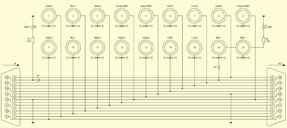
The D1 diode protects the diagnostic tester attached to the OBDII connector marked on the schematic diagram “OUT” against reverse polarity that may occur in the vehicle’s OBD2 connector (this situation may occur when the connector is interfered with in order to prevent the car being started by a thief). The D2 diode protects the diagnostic tester connected to the OBDII connector marked on the “OUT OUT” schematic diagram against reverse connection of the external power supply to the “BATT +” and “GND” banana sockets. The device uses two LEDs. The LED marked “OBDII” indicates the voltage present on pins 16 (plus power supply) and 4 (ground of the housing) when the CAN-BOX is connected to the vehicle’s OBDII connector, while the LED marked “Batt” indicates the external voltage applied to terminals 4 and 16.
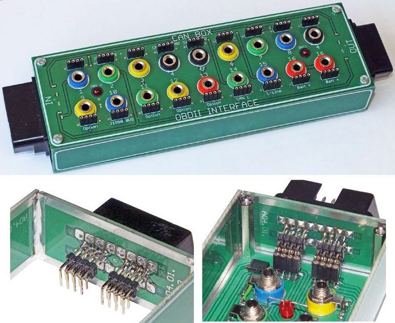
The CAN-BOX assembly diagram is shown in Figure 11. It is best to start the assembly by soldering R1 and R2 resistors and D1 and D2 rectifier diodes. Then mount all banana sockets in the holes on the front plate. The metal plates attached to the banana sockets should be bent and soldered to the goldpin leads. The “OBDII” and “Batt” LEDs must be properly bent and soldered as in photo 12. The OBDII connector and socket should be soldered to the attached circuit boards, paying attention to the numbering of the pins as described on the boards
![]()
FILE DOWNLOAD LINK LIST (in TXT format): LINKS-26574b.zip


