Although a stereo structure is often sufficient in home audio systems, a four-channel, that is, quadraphonic amplifier can provide a wider listening area and surround sound effect. In this project, a 4-channel audio amplifier structure was created using four LM3886 power amplifiers and two LM1036 tone control ICs.
The LM3886 LM1036 Quadraphonic Amplifier project includes Eagle CAD PCB, Schematic, Library, and LM3886 PSpice simulation files.
The circuit generally consists of several separate modules. The audio first enters the tone control preamplifier, where volume, balance, bass, treble, and loudness adjustments are made.
Then the signal is sent to the LM3886 power amplifier stage. A symmetrical power supply is used for the power stage, and a separate 12V supply is used for the preamplifier and fan control circuit.
A soft start circuit has also been added to limit the initial inrush current of the toroidal transformer.
For similar LM3886-based power amplifier applications, the LM3886TF speaker-protected stereo amplifier circuit article may also be a useful complement.
General Amplifier Block Structure
Contents
The block diagram below shows the basic structure of a classic audio amplifier. The low-level signal coming from a microphone, turntable, tape deck, tuner, or different audio sources first enters the preamplifier stage. Then it is transferred to the speaker through the intermediate amplifier, tone control, equalizer, and power amplifier.
Amplifier block diagram
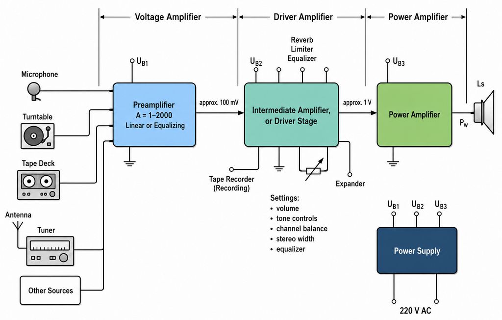
In this project, the structure has been expanded to four channels. In other words, the preamplifier and power stage are designed to support four separate audio channels: front right, front left, rear right, and rear left.
| Block | Function |
|---|---|
| LM1036 preamplifier | Volume, bass, treble, balance, and loudness control |
| NE5532 input buffer | Increasing input impedance and signal isolation |
| LM3886 power stage | Generating the power level required to drive the speakers |
| Symmetrical power supply | Supplying the LM3886 power stages |
| 7812 power supply stage | Supplying the preamplifier and fan control stage |
| Soft start | Limiting the initial inrush current of the transformer |
| Fan control circuit | Operating the fan according to heatsink temperature |
LM1036 Tone Control Preamplifier
The LM1036 IC is used in the preamplifier section. LM1036 is a stereo tone control IC.
For this reason, two LM1036 ICs are required for a four-channel system. The IC performs volume, balance, bass, and treble adjustments through its DC-controlled inputs.
In the schematic, the LM1036 connection for both stereo channels is shown. The use of the NE5532 op-amp in the input section is an important detail.
Here, NE5532 works like a buffer stage and increases the input impedance, preventing the source device from directly loading the LM1036 input.
Four-channel tone control preamplifier schematic with LM1036 and NE5532
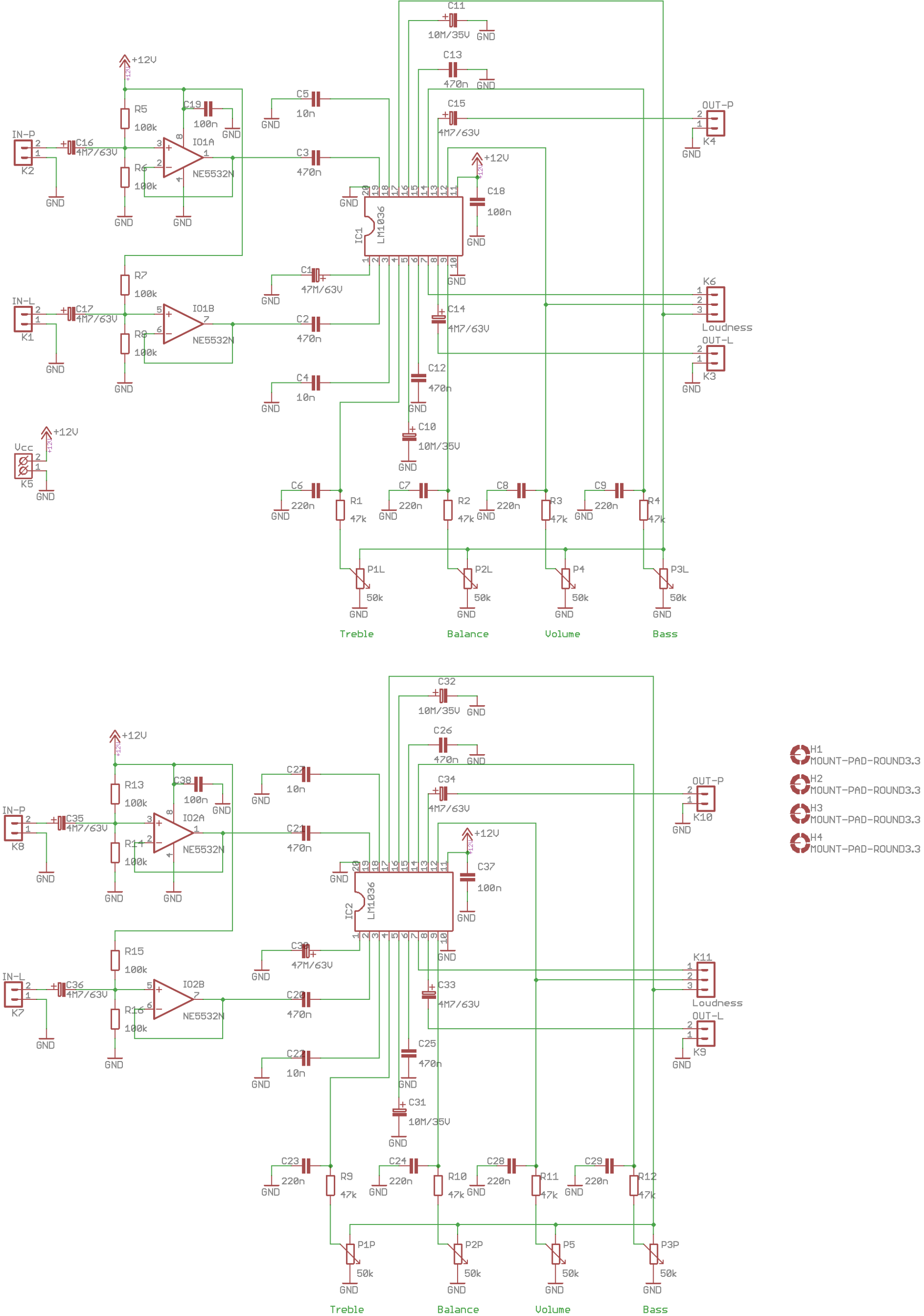
The control voltage taken from the reference voltage pin inside the LM1036 is applied to the potentiometers. Bass, treble, balance, and volume are adjusted with these potentiometers. The loudness connection can be used to support the perception of bass and treble at low volume levels.
- LM1036 has a stereo structure, two are used for four channels
- NE5532 acts as the input buffer
- Bass, treble, balance, and volume adjustments are made with potentiometers
- The loudness feature provides fuller listening at low volume
- Input and output capacitors block the DC component
For those interested in preamplifier and tone control circuits, the LM1036 tone control circuit article can also be examined to get to know this IC more closely.
LM3886 Power Amplifier Stage
In the power stage, one LM3886 is used for each channel. A total of four LM3886 ICs are required for the four-channel structure.
LM3886 is a popular power amplifier IC that can provide powerful and high-quality audio output with 8Ω speakers when proper cooling and a suitable symmetrical power supply are used.
In the schematic below, two separate LM3886 channels are shown on the same page. The input, feedback, mute, output, and power supply connections of each channel are separate.
Thus, two channels can be implemented on the same PCB; for four channels, two identical power stage boards can be used.
LM3886 dual-channel power amplifier schematic
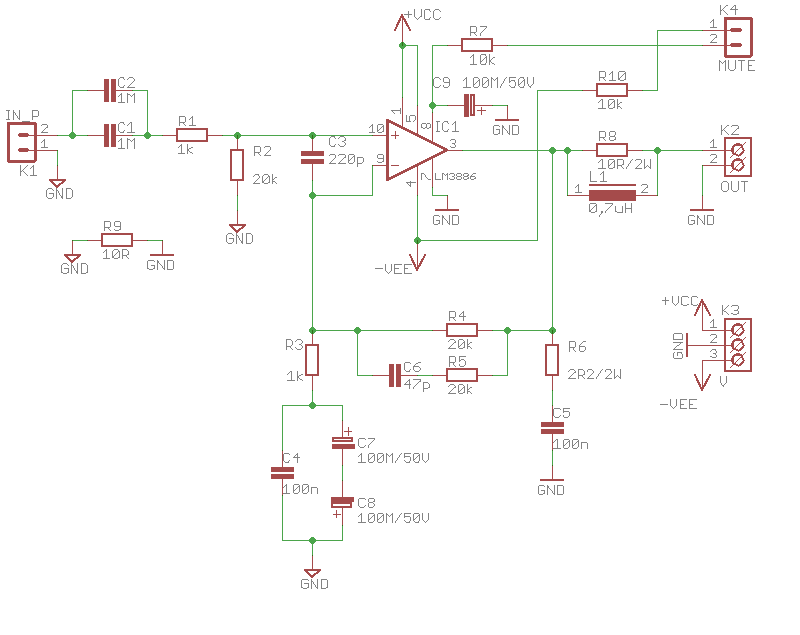
In the circuit, the input signal is applied to the LM3886 input through capacitors. The feedback resistors determine the gain.
The series coil and resistor structure used at the output increases stability with complex impedance loads such as speakers.
In addition, the Boucherot cell on the output side reduces the risk of high-frequency oscillation.
| Component Group | Description |
|---|---|
| Input capacitors | Block the DC component and pass only the audio signal |
| Feedback resistors | Determine the gain and frequency characteristic |
| 47pF / 220pF capacitors | Help with high-frequency stability |
| 2.2Ω + 100nF cell | Provides output stability as a Boucherot cell |
| 0.7uH coil | Relieves the output against speaker cable and complex load effects |
| Mute connection | Can be used for speaker protection or muting during power-on and power-off |
Active Fan Control Circuit
When LM3886 ICs operate at high power, they must definitely be cooled properly. In this project, a fan control circuit is also used in addition to a passive heatsink.
The circuit includes a TL071 op-amp, NTC thermistor, and BC337 transistor.
Fan control circuit with TL071 op-amp and NTC
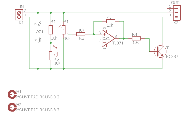
The NTC thermistor senses the heatsink temperature. As the temperature increases, the NTC resistance decreases.
TL071 compares the voltage coming from the thermistor with the reference voltage coming from the adjustment trimpot.
When the temperature reaches the set level, the output changes and the BC337 transistor drives the fan.
Since positive feedback is used in the circuit, some hysteresis occurs.
In other words, the fan starts operating around, for example, 50°C, and when the temperature drops slightly, it does not turn off immediately; it turns off when it falls to a lower temperature. This prevents the fan from constantly switching on and off.
- R5 NTC thermistor is the temperature sensing component
- P1 trimpot adjusts the fan activation temperature
- TL071 works like a comparator
- BC337 is the switching transistor that drives the fan
- Thanks to hysteresis, the fan does not operate unstably with chatter
Soft Start Circuit
In powerful audio amplifiers, large toroidal transformers and high-capacity filter capacitors are used.
This structure can draw a very high inrush current at first power-on. This current can blow the fuse, trip the breaker, or stress the rectifier bridge.
For this reason, a soft start section has been added to the circuit.
Soft start relay circuit with 4060 IC
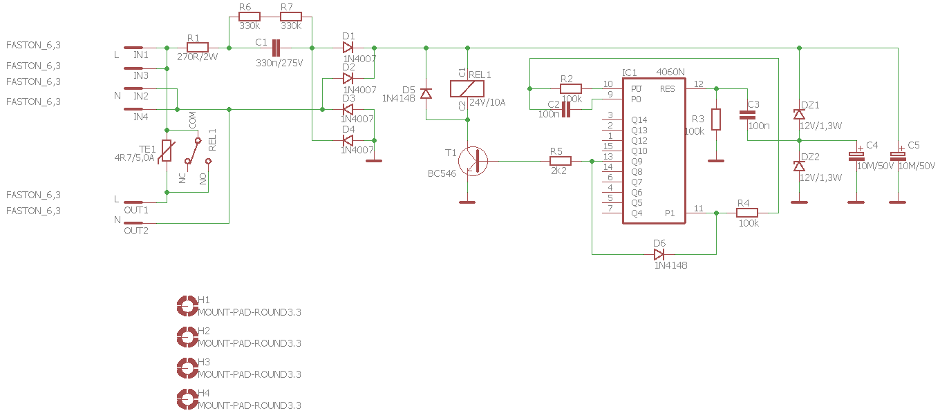
In this schematic, the 4060 IC performs the timing function. At first power-on, the transformer primary is energized through the series limiting component.
After a few seconds, the relay is activated, bypassing the limiting component, and the transformer enters normal operating condition.
The soft start circuit is especially important in amplifiers with large toroidal transformers.
Toroidal transformers can draw very high inrush current at first power-on depending on the magnetic state of the core.
Large filter capacitors also behave almost like a short circuit for a short time when they are empty.
| Circuit Section | Function |
|---|---|
| 4060 IC | Timing and delay generation |
| Relay | Bypasses the limiting component after the delay |
| NTC / limiting component | Reduces the initial inrush current |
| Zener diodes | Limit the control circuit supply |
| 1N4007 diodes | Rectification and protection functions |
Safety note: This soft start circuit operates directly with mains voltage. 220V AC connections can be lethal. Isolation, fuse, grounding, enclosure, and safe PCB clearances must definitely be taken into account.
Symmetrical Power Supply
A symmetrical power supply is required for the LM3886 power stages. In this project, positive and negative supply lines are created with a powerful toroidal transformer, bridge rectifier, and large filter capacitors.
Symmetrical power supply circuit for LM3886 power amplifier
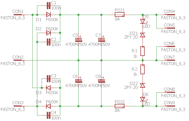
In the schematic, two separate rectification lines and large electrolytic capacitors on each line are seen. 4700uF / 50V capacitors are used to reduce power supply ripple. There is also an LED indicator section on the positive and negative lines.
In high-power amplifiers, power supply quality directly affects audio performance. If an insufficient transformer or small filter capacity is used, the supply sags during bass impacts, distortion increases, and channel separation may deteriorate.
- A symmetrical power supply is required for LM3886
- Large filter capacitors reduce low-frequency ripple
- Power supply cables should be kept short and thick
- The star grounding method can reduce hum
- Fuse and isolation should not be neglected
For those interested in amplifier power supply design, the Amplifier Power Supplies article may also be useful in terms of rectification, filtering, and current capacity.
12V Supply for the Preamplifier
A separate 12V supply is used for the preamplifier, fan control circuit, and auxiliary stages. This section includes a small EI type transformer, bridge rectifier, filter capacitor, and 7812 regulator.
Preamplifier and fan supply circuit with 7812 regulator
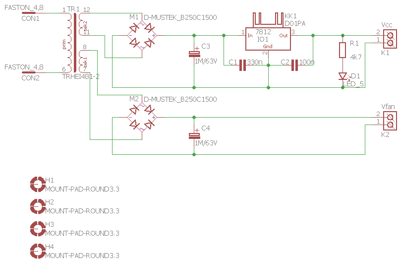
Keeping the preamplifier supply separate from the power stage is a good choice. Because the high current pulses and large speaker currents of the power stage can create hum or interference in the sensitive preamplifier stage. Using a separate supply reduces this effect.
| Component | Function |
|---|---|
| EI transformer | Provides low-power AC supply for the preamplifier and fan |
| Bridge rectifier | Converts AC voltage to DC voltage |
| 1000uF capacitors | Filter the rectified voltage |
| 7812 regulator | Produces a stable 12V output |
| LED indicator | Shows the presence of supply voltage |
PCB and Modular Structure
The most logical setup for this amplifier is a modular structure. The preamplifier board, power amplifier boards, symmetrical power supply board, 12V power supply board, soft start board, and fan control board can be prepared separately. This makes testing, maintenance, and troubleshooting easier.
Especially on LM3886 boards, the power supply and speaker tracks carrying high current should be kept wide. Input signal tracks should be routed away from the power output and transformer cables. If input GND, power GND, and chassis connections are combined randomly, hum may occur.
- Power supply tracks on power stage boards should be wide
- The input signal can be carried with shielded cable
- Distance should be left between the transformer and the preamplifier
- Potentiometer cables should be kept short
- LM3886 heatsink insulation should be checked
- The mains side of the soft start board should be safely enclosed
First Startup and Test
This type of high-power amplifier should not be tested directly with speakers connected. During the first startup, it is safer to use a series lamp, current-limited variac, or laboratory test setup. First, the power supplies should be measured, and then the preamplifier and power stages should be checked separately.
| Test Step | Expected Condition |
|---|---|
| Soft start test | The relay should pull in with a delay of a few seconds |
| Symmetrical supply test | The positive and negative lines should be balanced |
| 12V supply test | A stable 12V should be seen at the 7812 output |
| LM1036 test | Volume, bass, treble, and balance adjustments should work |
| LM3886 output test | DC voltage at the speaker output should be low |
| Fan control test | The fan should turn on when the NTC is heated |
Before connecting speakers, the DC offset should be measured at each LM3886 output. If there is high DC voltage at the output, speakers should not be connected. Also, using a low-level signal and dummy load resistor in the first test is safer.
Brief Evaluation
This quadraphonic amplifier prepared with LM1036 and LM3886 is a very educational project in terms of classic analog audio electronics. While volume, bass, treble, balance, and loudness control are performed on the preamplifier side, a powerful output is obtained by using a separate LM3886 for each channel in the power stage.
The project should be considered not only as a power amplifier, but as a complete audio system. Because for a successful result, the preamplifier, power stage, symmetrical power supply, 12V auxiliary supply, fan control, soft start, and mechanical cooling must all be designed correctly together.
With correct PCB layout, solid grounding, sufficient transformer power, good cooling, and careful first startup, this structure can be turned into a powerful four-channel audio amplifier for home use.
Source: dspace.vut.cz/items/687f4265-fabd-4e42-8420-cc6f58cfa141