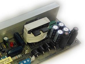
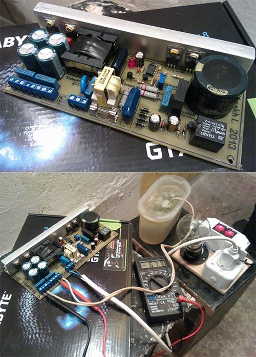
SMPS designs designed as IR2153 amplifier power source based on IR2153 Integration. The 300W version gives 2X44V DC. Circuits have Short circuit protection.
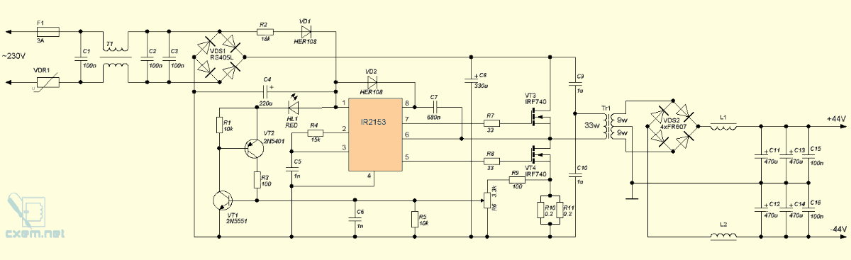
IR2153 SMPS 300W Version: In general, IR2153 Supply voltage is taken over 220v filter capacitor, that is, over + 310V resistor or mosfet regulator. In these circuits, 18k 2w resistor is connected to 220V AC line in series and it is rectified with HER108 fast and IR2153 supply voltage is provided. There are several advantages to feeding this way.
1. Reduces the power used in extinguishing resistance. This reduces heat generation on the board and increases the overall efficiency of the circuit.
2. It differs from the power supply via the + 310V bus and provides a lower level of ripple in the drive supply voltage.
Protection against overloads and short circuit is carried out with a pair of transistors 2N5551 2N5401 transistors. Working as a current sensor, this part is activated according to the voltage drop on the 0.2 ohm shunt resistor connected in parallel.
In the event of a short circuit or overload, when the voltage drop in R10 R11 reaches a predetermined value, the VT1 2N5551 has a value in the head of more than 0.6 – 0.7V, the protection works and cuts the supply voltage of the IR2153 circuit by pulling it to the ground. As soon as overload or short circuit disappears, the power supply continues to operate normally. LED indicates protection is activated.
Transformer core used in IR2153 SMPS 300W Circuit ER35-21-11. The primary winding is 33 turns of 2 wires connected in parallel with 0.63 mm2. The secondary winding will be connected in parallel with 3 pieces of 0.63 mm2 wire and 2x 9 turns will be wound. Note: It is healthier to connect Series 10OHM 5A ntc to 220v Input
IR2153 300W SMPS Circuit Diagram
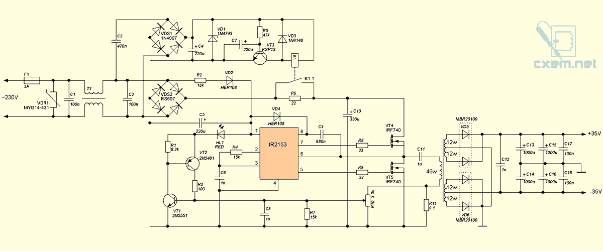
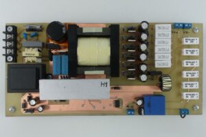
2X35V 500W SMPS Circuit
The power is higher than the other one, continuously 300w instantly restores 500w power working frequency 50Khz in this design, soft start circuit with relay is added. Short circuit protection is the same as in the other version.
Transformer used in the circuit ETD29. The primary primary winding is wound 46 turns from 2 pieces of 0.8mm wire. The Sekondar winding is connected in parallel with 2 pieces of 0.8mm wire and is wound in 2 × 12 turns. Actually, there is no need for 4 × 12 wraps, but the author deems this appropriate…
There are scheme and material lists of source drawing files made in two circuits with the PCB drawings Sprint Layout Program.


Beautiful work – Thanks for the motivation.
Bon schéma merci, je veux utiliser ce dans mon alimentation 2x80v.
I built this smps ,using every thing on the diagram and wound thetransformer accoirding to your specs. The 0.8mm wires are much too thick to wind all the turns onto the ETD29 bobbin. The core itself cannot handle 300watt according to the data sheet. The moment I switched it on the output rectifier combination burns out. I replaced them but then the MOSFETS burnt out. The pulses from the 2153 are correct but is it possible that it this IC can cause that problem ? Can a fake IC cause that ?
There is goof up in the output rectifier after the secondary bridge rectifier diodes. The center taps of the two secondary windings must be connected to round. But if you see in the diagram but the cathodes of lower two diodes are connected directly to the ground. That caused your output rectifiers to fry.
The schematic is okay and not(!) wrong, because the MBR20100 have a common cathode pin, and therefore no other connection would make any sense to get the -35V rail.
My believe is, that George might have some issues with the isolation of the diodes to the heatsink. After you have installed everything on the heatsink make sure that there is no connection between both pin 2 of the TO-220 case of the double-diodes. Use an Ohm-Meter to check that. Never forget to isolate the M3 screws from the metal part of the TO-220 case and always use silicone/captone/Glimmer or even Al2O3-ceramic pads between the TO-220 case and the heatsink.
Another reason could be that the primary windings are either completely mixed up or not connected in the correct orientation (i.e. polarity). That can be checked by using a sine generator connected to the primary (of course with the transformer not populated on the PCB). Set the generator to a few 10 kHz and some amplitude that produces a noticable output voltage. Connect an oscilloscope with CH1 to the generator as a reference and use CH2 at the secondaries to check the phase offset. Make sure that you observe always the same phase shift when you look at each (of the 4) secondary winding assuming the top connection in the schematic is (+) and the bottom connection is (-).
Usually in schematics transformer windings are marked with a little dot to show points of same polarity.
There are two schematics. 1. 300 W showing shunt resistor connected to MOSFET(low side). 2. 500 W with delayed on showing shunt resistor connected to primary winding. which one is correct? Again as per the source link provided shunt resistor connected to MOSFET(low side). PCB design shunt resistor connected to primary winding. Please advise.
Hello,
Both versions can work; the shunt position is just different.
In the 300 W schematic, the current sense resistor is placed in the low-side MOSFET source path. It mainly senses the low-side MOSFET current.
In the 500 W version, the shunt resistor is placed in the primary transformer return path. This senses the primary current of the transformer more directly, including load-reflected current and possible transformer saturation current.
For higher power, placing the shunt in the transformer primary return can be more suitable because it does not lift the MOSFET source as much and keeps the gate drive reference cleaner. So the PCB version with the shunt in the primary winding return is not necessarily wrong; it is just a different current-sensing method.
However, this is still a simple overload / short-circuit protection method, not a precise cycle-by-cycle current limit system.