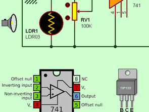
The circuit diagram you see in the picture works as a dark switch with the LDR on it. The circuit consists of four resistors, a 741 opamp, two potentiometers (optional trimpot available), an LDR, a switching TIP122 transistor and a lamp. In the circuit, the value of the resistor R1 is directly proportional to the internal resistance of the LDR and operates as a voltage divider between 6-12V.
Depending on the internal resistance of LDR1, the task of the RV1 potentiometer was used for the degree of sensitivity to the amount of light that would fall on LDR1. Of course, RV1 is also a voltage divider. For this reason, the resistance value divided by LDR1 and R1 materials is compared with the resistance value divided by RV1 by U1.
Assuming that the RV1 potentiometer is 6V and that LDR1 is in the dark, the voltage at the non-inverting input of U1 will be a positive voltage at the output of U1 since the internal resistance of LDR1 will be high, since it will take a value close to or slightly higher than 6V.
Dark Switch Circuit Schematic Diagram
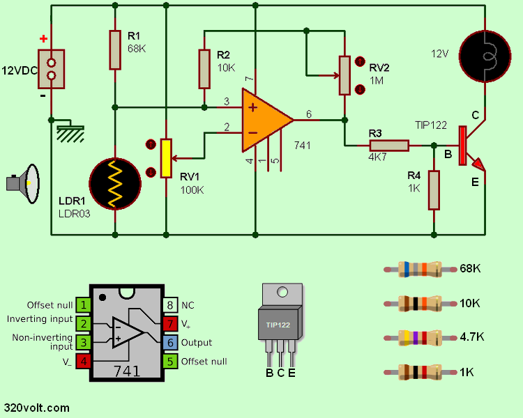
This will trigger Q1 via R3, which will allow L1 to light. When L1 gives light, a certain decrease in the internal resistance of LDR1 will be observed, which will cause the opamp output to 0V and T1 will go to the TIP122 transistor and L1 will go out.
It should be noted, however, that assuming that the resistor R4 is absent, there will be a continuous voltage on the opamp output 741, thus preventing the transistor Q1 from going into the cut. The resistor R4 will draw the voltage of the transistor Q1 on the ground to ground.
The RV2 potentiometer will react to U1 and its gain will change. When the resistance of the RV2 potentiometer is large, the opamp will work as a comparator and when small, it will work as an amplifier.


Circuit de commutation sombre avec 741 Opamp
Le schéma de circuit que vous voyez sur l’image fonctionne comme un interrupteur sombre avec le LDR dessus. Le circuit se compose de quatre résistances, un ampli op 741, deux potentiomètres (trimpot en option disponible), un LDR, un transistor TIP122 de commutation et une lampe. Dans le circuit, la valeur de la résistance R1 est directement proportionnelle à la résistance interne du LDR et fonctionne comme un diviseur de tension entre 6-12V.
En fonction de la résistance interne du LDR1, la tâche du potentiomètre RV1 a été utilisée pour le degré de sensibilité à la quantité de lumière qui tomberait sur le LDR1. Bien sûr, RV1 est également un diviseur de tension. Pour cette raison, la valeur de résistance divisée par les matériaux LDR1 et R1 est comparée à la valeur de résistance divisée par RV1 par U1.
En supposant que le potentiomètre RV1 est de 6 V et que LDR1 est dans l’obscurité, la tension à l’entrée non inverseuse de U1 sera une tension positive à la sortie de U1 car la résistance interne de LDR1 sera élevée, car elle prendra un valeur proche ou légèrement supérieure à 6V.
Schéma du circuit du commutateur sombre