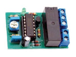
An uncomplicated layout that will perfectly test sift wherever necessary delay the application of any device. Delay time it can be adjusted from about 2 to 120 seconds. It may find use on for example, in a car, in the role of a system delaying the application of any receiver, e.g. The main element The system is integrated, programmable timer type cd4541.
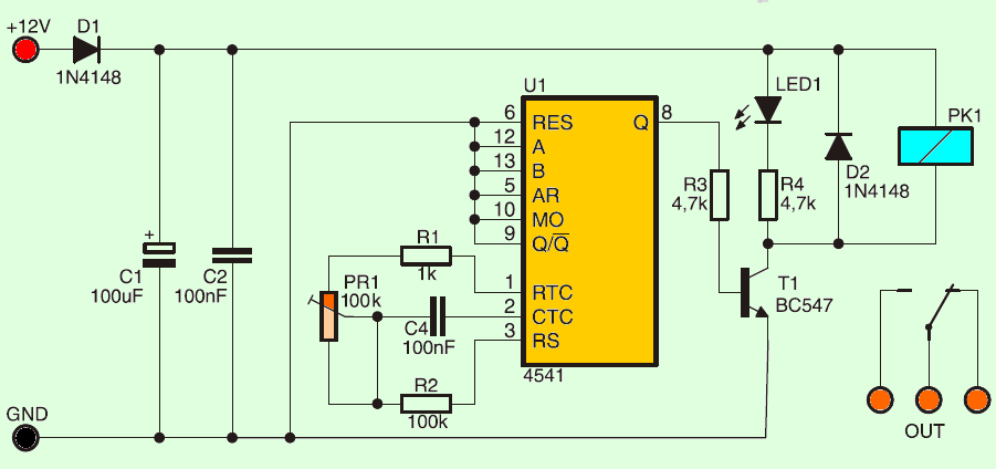
In the proposed solution it has been configured to work as a switch with adjustable delay time. Resistors R1, R2, PR1 and capacitor C3 are components of the internal oscillator of the U1 system, they have affect the length of the measured delay time. It can be made with the PR1 potentiometer calibration. From the Q output of the U1 circuit through the resistor R3 and further the transistor T1 is controlled relay attached to the load.
Diode D2 protects the transistor from damage during switching the PK1 relay, and the LED diode signals its operation. The installation of the system is typical and he shouldn’t cause problems. The device should be powered up voltage of 12 V from the power supply, battery or accumulator. The model copy was used relay with 8A permissible load current at 230 VAC.
Adjustable Delay Circuit Schematic Diagram
![]()
FILE DOWNLOAD LINK LIST (in TXT format): LINKS-26535b.zip


Circuit de retard réglable
Une mise en page simple qui testera parfaitement le tamisage partout où cela est nécessaire retardera l’application de n’importe quel appareil. Le temps de retard peut être ajusté d’environ 2 à 120 secondes. Il peut par exemple être utilisé dans une voiture, dans le rôle d’un système retardant l’application de n’importe quel récepteur, par ex. L’élément principal Le système est intégré, minuterie programmable type cd4541.
Dans la solution proposée, il a été configuré pour fonctionner comme un commutateur avec un temps de retard réglable. Les résistances R1, R2, PR1 et le condensateur C3 sont des composants de l’oscillateur interne du système U1, ils ont une incidence sur la longueur du temps de retard mesuré. Elle peut être réalisée avec l’étalonnage du potentiomètre PR1. De la sortie Q du circuit U1 à travers la résistance R3 et en outre le transistor T1 est un relais commandé relié à la charge.
Yukardaki devrede 4541 entegresinin + voltajı nereden aldığını göremedim. Bu devreden eminmisiniz.
evet şemada yok unutulmuş olabilir. orjinal pcb çizimide sorun yok. benim çizimde (lay6) besleme hattı bağlı değilmiş düzenleme yapıldı