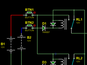
Simple circuit with relay that directs output at the correct polarity when DC input is reversed. In reverse polarity protection, there is no output in the wrong connection. With this circuit, it gives output in all kinds of connections.
In this connection there is a circuit that is inserted between the power supply and the appliance, which automatically ensures the correct polarity of the supply voltage at the terminals of the appliance at any polarity of the source. Two relays are used to switch the polarity.
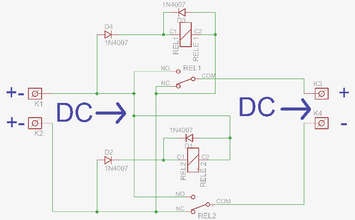
voltage on their contacts, which is advantageous for powering, for example: radio stations from the car battery. The DC power supply is connected to the automatic polarity converter to the terminals K1 K2, the appliance supplied to the terminals K3 (+) K4 (-). When the power supply is disconnected, both relays are inactive, the connection between input and output is broken and the output is short-circuited by contact REL1! After connecting a source with any polarity, it is not possible for even a brief moment
get the opposite supply voltage to the input of the appliance and destroy it. If we connect the power supply so that its positive pole is on terminal K1 and negative on K2, relay RELE 1 is activated via diode D1 and contact REL1 is flipped.
Positive voltage is applied from terminal K1 to output terminal K3 via this contact. The negative pole of the power supply at input terminal K2 is connected to output terminal K4 in the quiescent position via contact REL2. When the supply voltage is connected so that the negative pole is at terminal K1 and positive at K2, relay RELE2 is activated via diode D2 .An negative voltage is applied via this contact from input terminal K1 to output terminal K4. The positive pole of the power supply at input terminal K2 is connected to output terminal K2 via contact REL1 in the rest position.
Diodes D3 and D4 are connected in parallel to the relay coils, through which the currents flowing through the coils are closed after the supply voltage is disconnected. Without these diodes, high voltage pulses would be generated on the coils when the supply voltage is disconnected, which could damage the supplied appliance.
Automatic Polarity Stabilizer Circuit Diagram
What is relay, how does it work, etc. in SPDT Relay and DPDT Relay Circuits article. Besides the information, simple relay circuits were shared in this circuit, similar structure ..
Eagle cad pcb, proteus simulation
FILE DOWNLOAD LINK LIST (in TXT format): LINKS-27239a.zip
source: elektronic.cekuj.net


