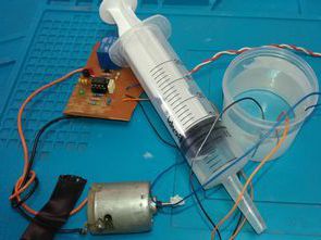
Simple 555 circuit. The water tank filling circuit is based on the NE555 timer IC. By measuring the water level in the tank, it automatically starts the water pump motor at low water level and stops the water motor when the water in the tank reaches the specified level. The circuit can be used for different purposes, such as a flood alarm circuit and so on.
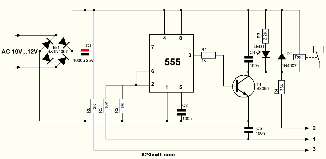
You can use a transformer with 10V…12V AC output or a DC adapter with 12V output. If you are going to run the circuit with a 12V DC adapter, there is no need for rectifier diodes. 100Uf can be used in a 1000uf capacitor.
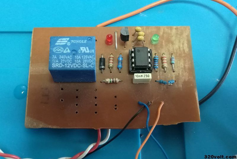
The power of the relay on the water level control tank filling circuit is 10 amperes, high power pump motors can be connected, and the current drawn on the label on the motor is written. You determine the fuse value according to the motor current information.
Note: 2 contacts of the relay are used, but when the relay is not pulled, I gave an output in a closed contact for the operation of another device or for different scenarios, by adding an additional relay or circuit, various works can be done. Relay Circuits (detailed in the video
PCB printed circuit drawing of automatic water tank filling circuit prepared with Sprint layout 6 PCB dimensions 58x43mm
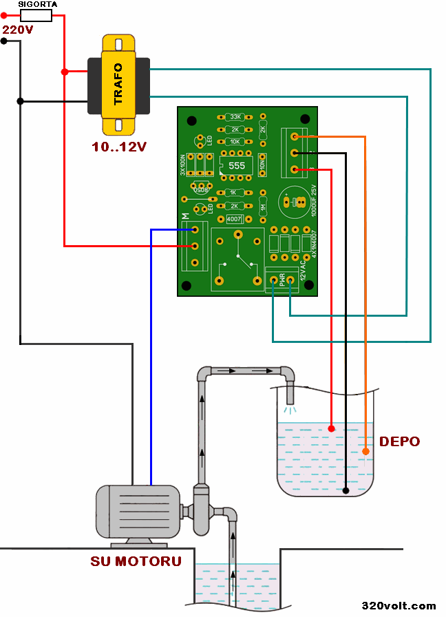
Automatic Water Tank Filling Circuit Diagram
Water level sensor connection;
The number 2 sensor is placed just above the bottom of the tank.
The number 1 sensor is placed in the middle of the tank.
The sensor number 3 is placed in the upper limit section of the tank, when the water reaches the level of this sensor, the engine stops.
Water sensor construction;
The construction of the sensors to be placed in the water tank is simple. 1 PVC pipe and 3 single core Nya electrical cable in the size suitable for your warehouse are sufficient.
When you strip the outer white part of the cable, 3 wires in blue, brown and yellow colors will flash inside. After fixing them to the PCV pipe with a cable tie, you should open the ends with a side cutter or pliers for 1 cm. The cable does not need to be completely peeled, only the end will be opened. You’d better cover the bottom of the open end with silicone adhesive around the plastic-coated part.
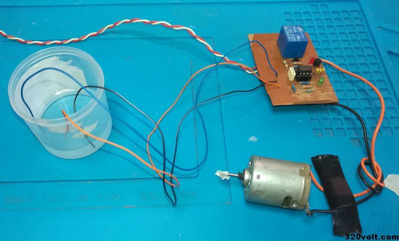
Automatic Water Tank Filling Motor Wiring Diagram
FILE DOWNLOAD LINK LIST (in TXT format or file): 27964a.rar pass: 320volt.com


