In applications for external starting of the washing machine engine, the biggest missing torque is the lack of power control, starting the engine by applying direct voltage only provides speed, and the engine stops at the slightest strain. There are circuits using the TDA1085C universal motor speed control integrated for full control. TDA1085 is an advanced controller, but its price is high and the circuit installation is a bit complicated.
The circuit I use to start the washing machine motor is simpler, cheaper, more stable and has a soft start feature compared to the TDA1085C integrated circuit.
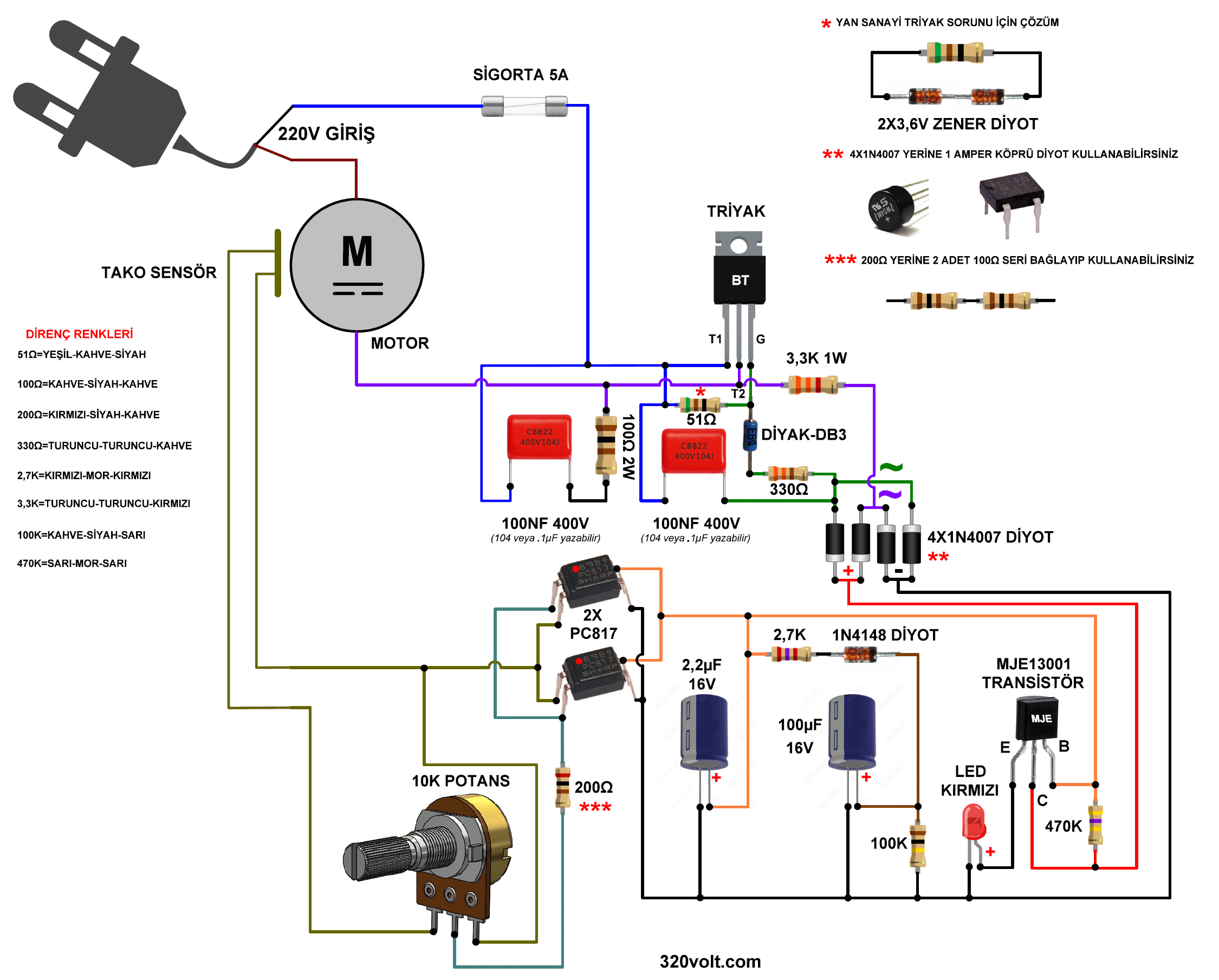
The circuit consists of PC817 optocouplers, passive components and triacs, diodes, transistors and diodes. ILD621 dual channel optocoupler can be used instead of 2 PC817. The component you need to pay attention to that will cause problems is the triac. Aftermarket triacs may operate problematically, they cannot be triggered or controlled.
To solve this problem, a zener diode between 3.3v…3.9V is connected in reverse-series to the 51-OHM resistor connected to the G leg of the triac. I left room for this connection on the PCB. Since the triac I use is original, I did not use the zeners * (I also had a aftermarket problem, details in the video). If everything is correct and you experience the problems I mentioned, make this zener diode connection.
You can use MJE13002 instead of MJE13001 transistor. Do not use high power transistors. These transistors have higher leakage currents. The circuit will work, but it may cause problems in the future.
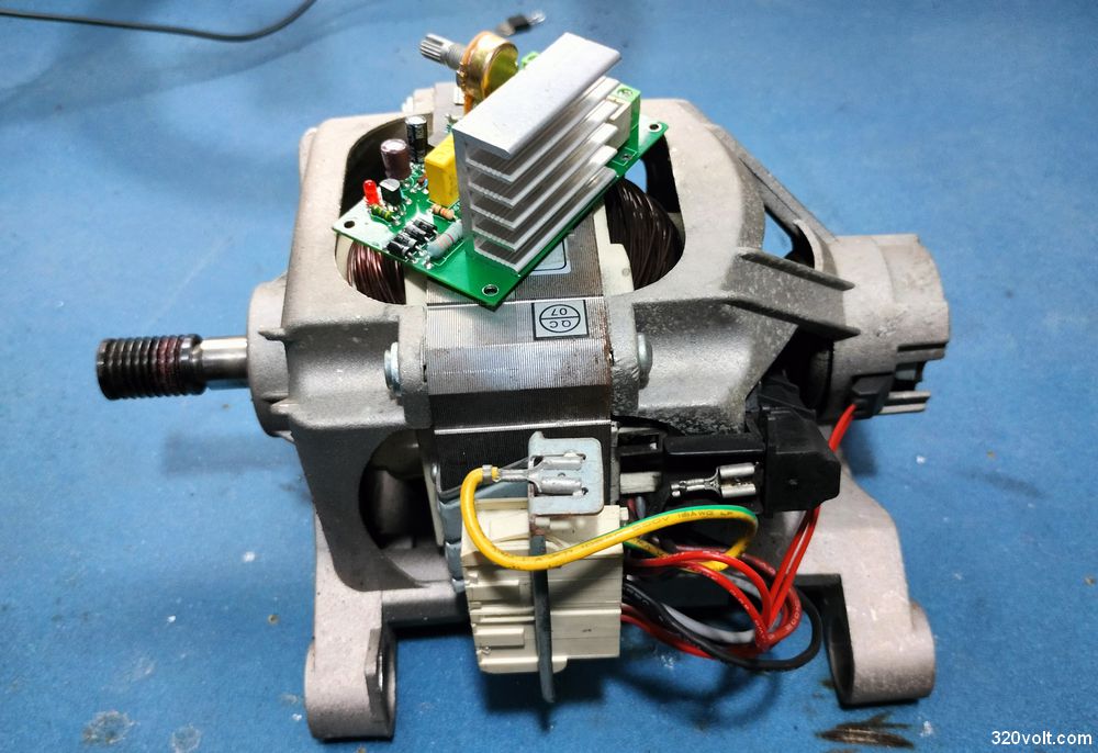
In order to run the washing machine motor with 220V, we first need to short-circuit one of the brushes with the motor coil winding. This process is shown in the block diagram below, which contains the description and connection information of the washing machine motor.
Washing machine engine stands for block diagram
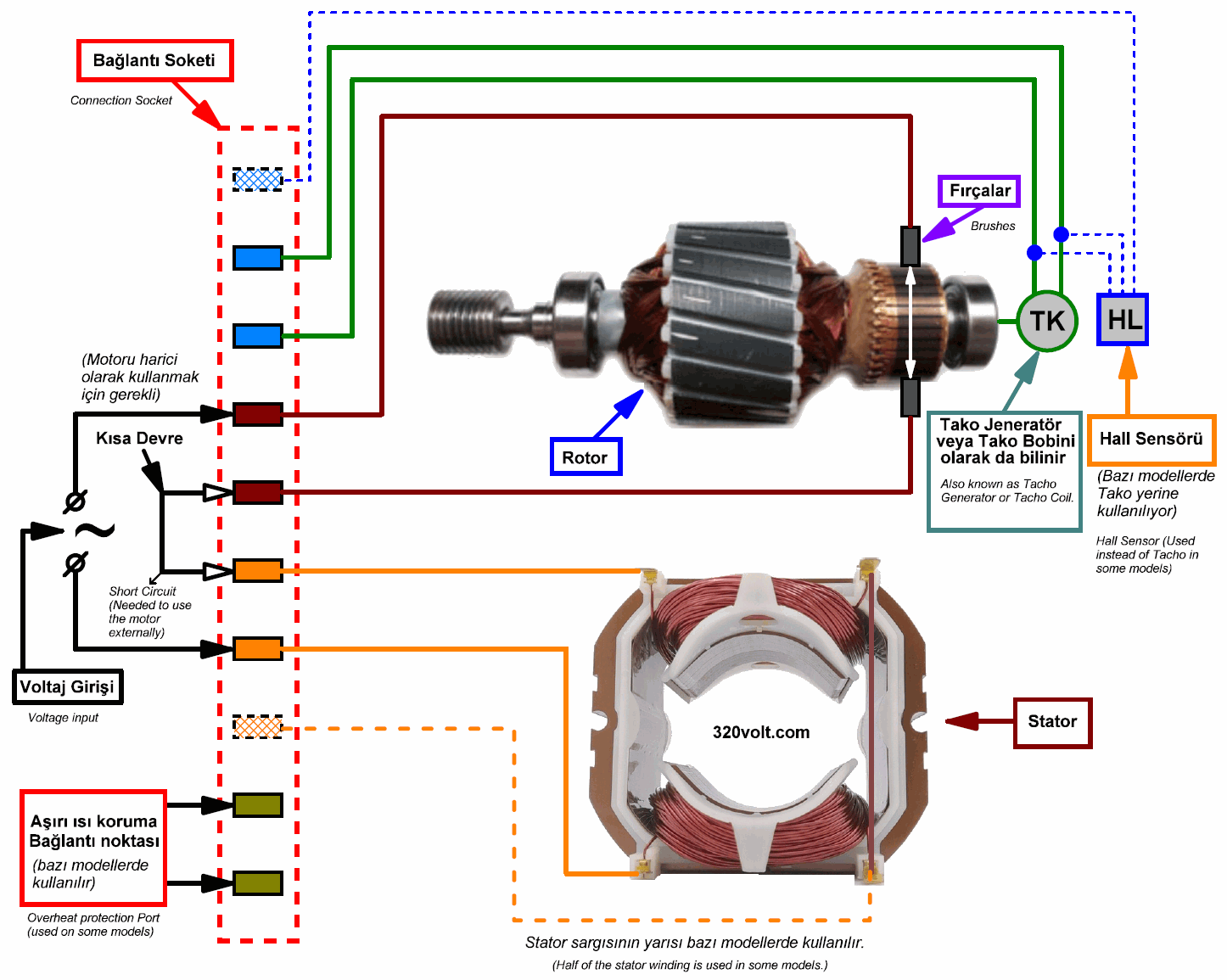
Note: As you can see in the block diagram, some models use Hall sensors instead of tacho coils. The circuit is not suitable for this type of motors, but most machine engines use tacho coils.
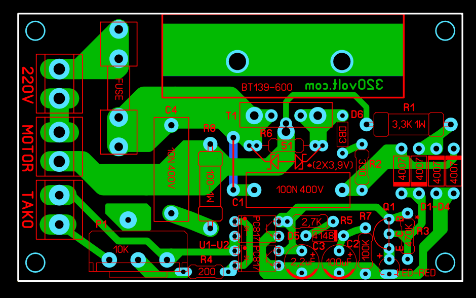
Washing Machine Motor Driver Circuit Diagram
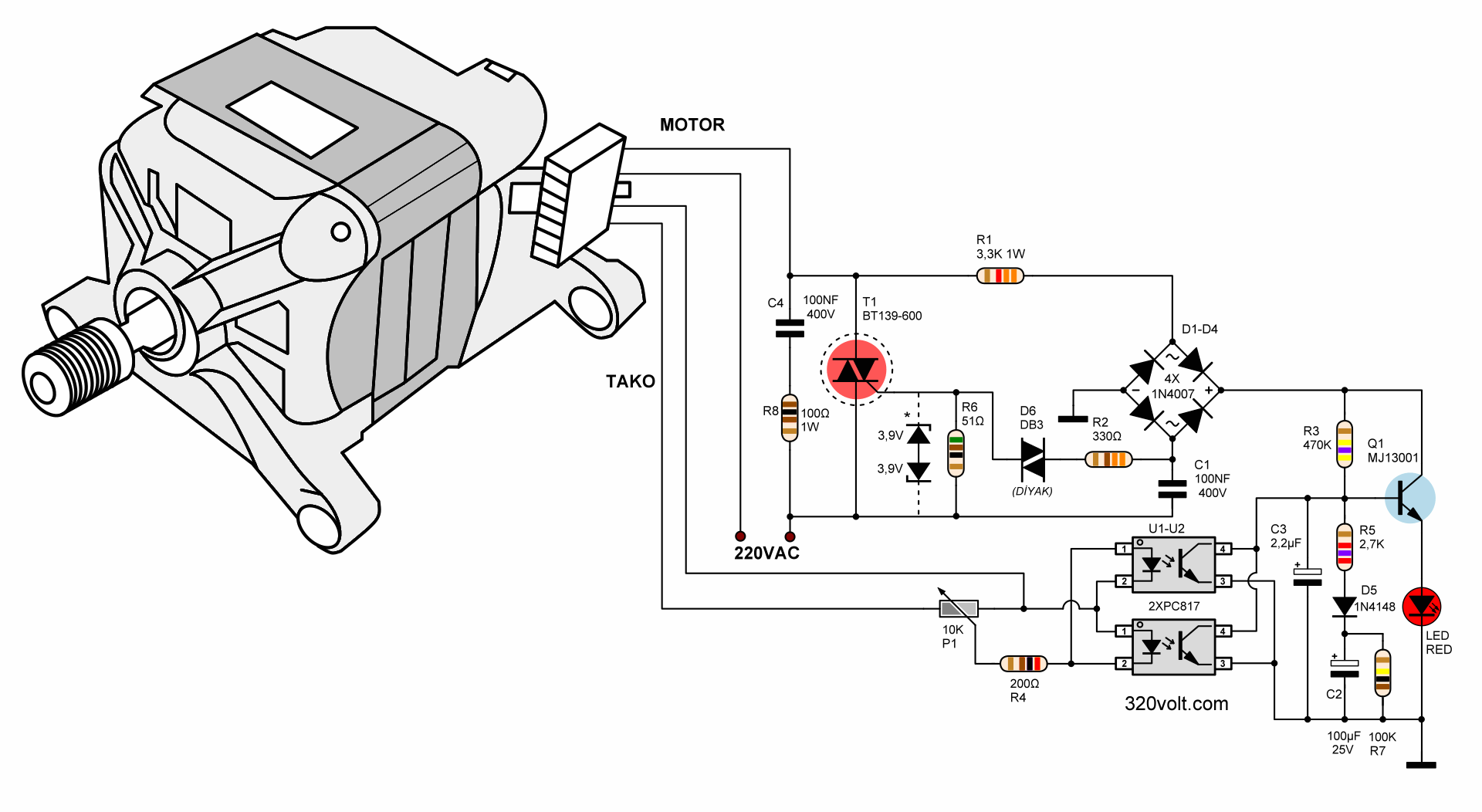
Washing Machine Motor Driver Basic Circuit Diagram
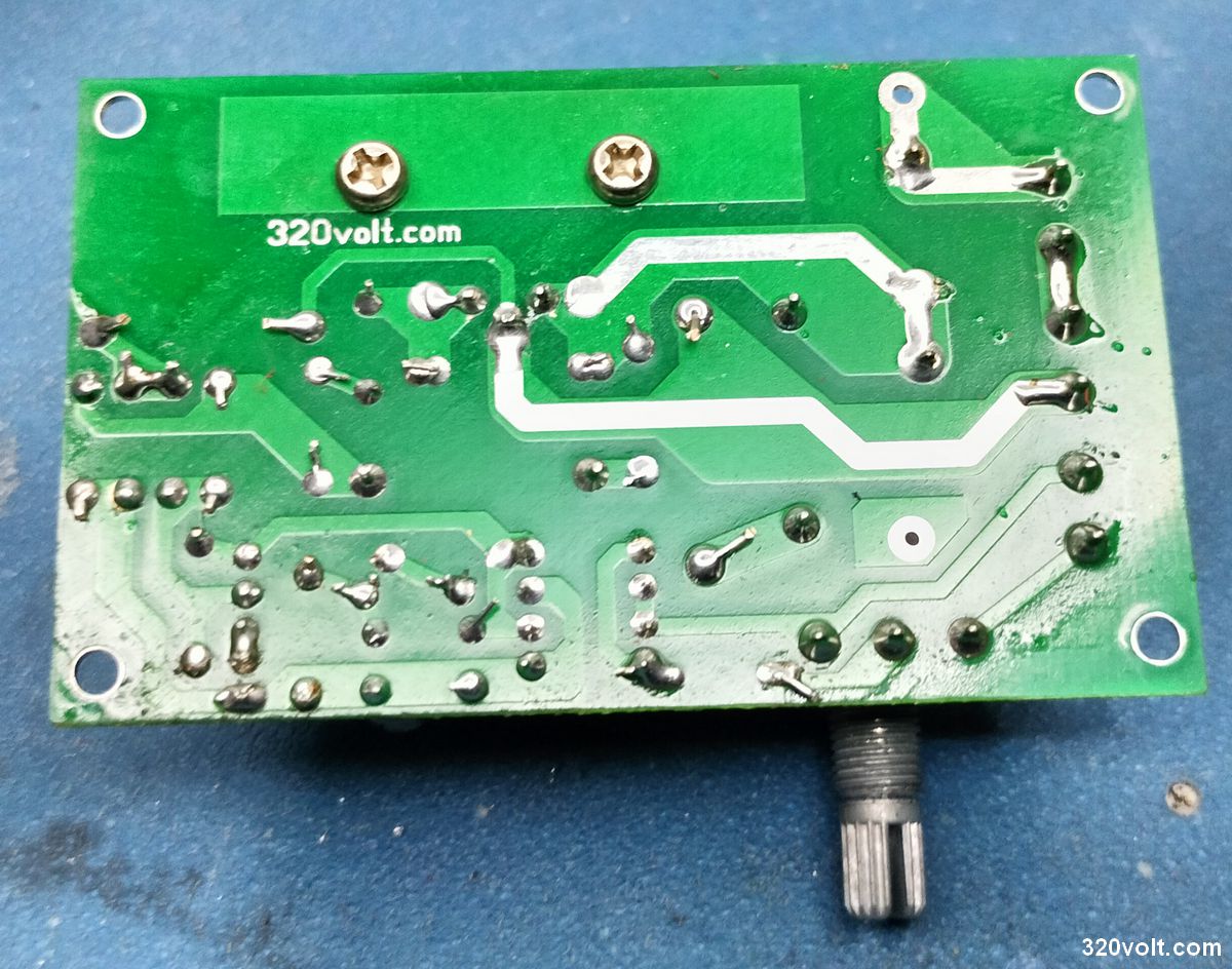
PCB design was made with Sprint Layout 6 program. Its dimensions are 76.6×45.9mm and it is single-layered. For the triac, T220 and TO247, TOP3 sheath mounting was made.
Washing machine motor driver circuit details;
C2 = 100uF Soft start capacitor. It is not recommended to use above 150 uF. The voltage on it cannot be greater than 2.2V. Delay time for motor switching on R5+C2, = charge curve slope, motor acceleration time. R7 – C2 discharge time for next soft start cycle (at 51k it is about 2-3 seconds)
C3 = 1uF To soften shocks, especially at low speeds. From 1µF to 4.7µF, a maximum of 47µF is recommended. If possible, use a low ESR quality capacitor (the standard ones I use).
C4 = 100nF 400V DC or 275V AC This component is the capacitor of the RC circuit against interference and high voltage fluctuations on it.
A value between R1 = 3K….5.1K can be used. (0.5W….1W)
A value between R2 = 51….470 Ohms can be used.
R3 = A value between 300K and 1M can be used. If this resistor is too large and cannot fully turn on the transistor, the maximum speed will not be reached and the minimum speed will decrease. If this resistance is too small, the minimum speed will increase. It is good to stay within the range of 330k – 470k.
R4 = 200 Ohm Optocoupler to protect LEDs from excessive tacho voltage.
A value between R5 = 100 Ohm….5.1K can be used.
R6 = A value between 36….51 Ohms can be used. A 51 Ohm resistor is recommended in the data sheets of the triacs.
R7 = A value between 51K…150K can be used.
R8 = A value between 39… 100 Ohms can be used.
P1 = Potentiometer A value between 2K….10K can be used. The lower the value, the more the tacho is steered and the minimum achievable speed increases slightly.
You can use triac with T1 = 16 Amps and at least 400V. BT139-600E (16A 600V), BTA16-800 (16A 800V), BTA24-800 (24A 800V), BTA40-800 (40A0600V), BTA41-800 (40A 800V)
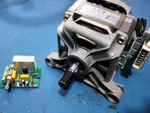
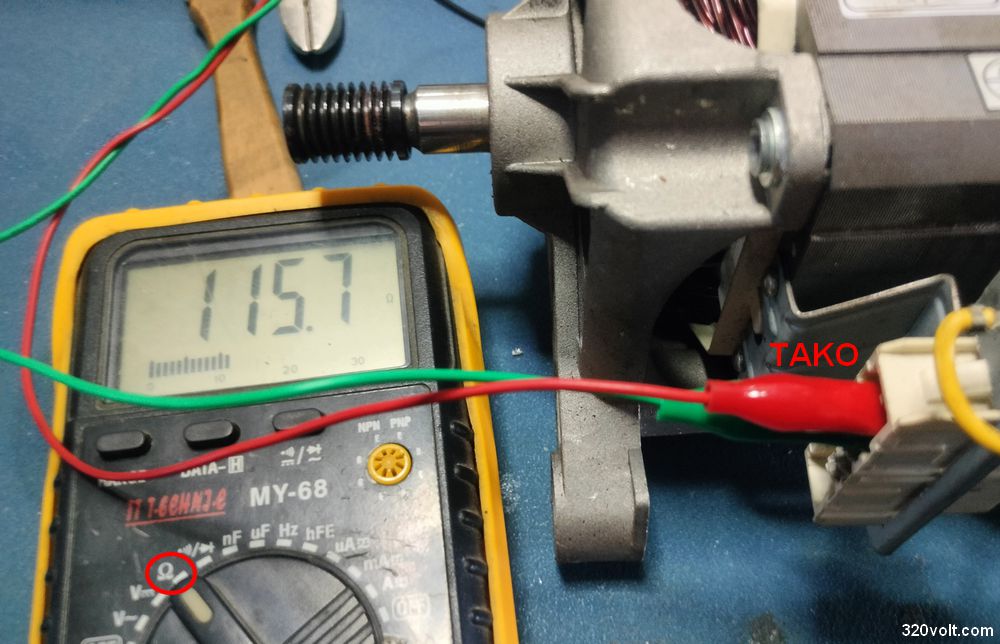
Tacho Generator Coil Test, Measure
I burned out the tacho sensor of the motor I was using for the wood lathe as a result of incorrect connection. Fortunately, taco coils are sold separately in the market. Information about tacho generator coil measurement and testing may be useful for similar or malfunction situations.
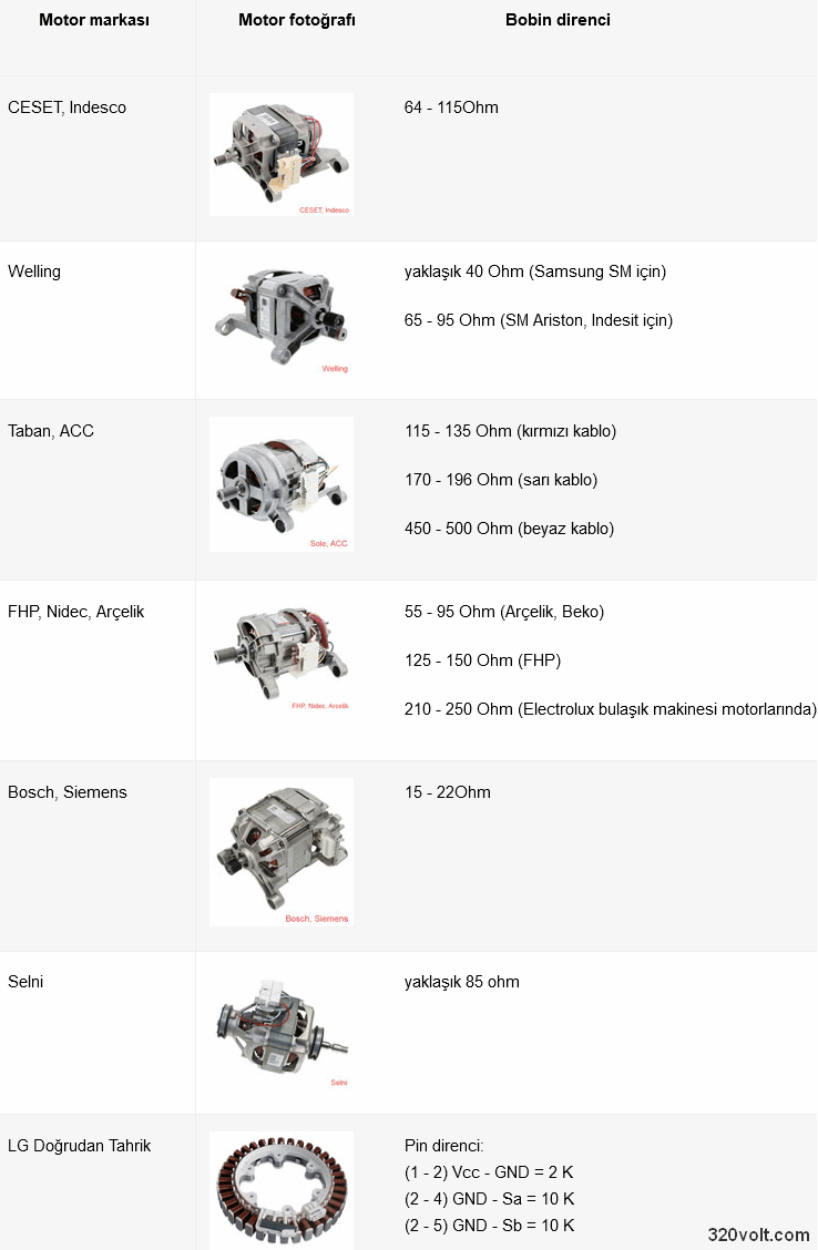
The tacho sensor has internal resistance, it varies depending on the brand and model, but generally it is between 60-120-ohms, you can measure it with the multimeter resistance measurement level. In addition, when the motor is running, it produces voltage between 0-70VAC depending on the rotation speed. When you put the multimeter in AC voltage measurement position and turn the motor shaft by hand, you will see a voltage of 0.5….1VAC.
CAUTION: The circuit works with high voltage. Be careful about capacitor connections. If you connect the + – poles in reverse, there may be large explosions at high voltage. Before operating the circuit, use a Fused Power Line and protective glasses.
Thanks for your feedback; @Bronislav Szkokan

Update: Suggestions from a reader who applied the circuit and got good results:
I built and got this circuit working. Thanks to the author.
I used it on a belt sander. Here are some tips for anyone who wants to use it:
1- If you plan on using it at low speeds, a BTA24 is a must. A BTA16 has a short lifespan. If you absolutely must use a BTA16, make sure it’s the B series. The sensitive ones don’t work.
2- I couldn’t get the PC817 SOT-4 package to work. I used an LTV-816.
3- For those new to iron-on printing like me, be careful and print the toner with the highest quality. Otherwise, the card won’t work. It’s best to get a ready-made one from the link provided.
4- Definitely use the fuse. 5 amps is perfectly sufficient for a 600-watt Arçelik.
The small heatsinks for the 5-to-220 are weak. You’ll need a beefy one like the one in the video; their lifespan will be short.
6- I couldn’t find an MJE13001. You can use it by bending the B and C pins of the MPSA44. It works.
Thanks again to the author, it is a very useful and affordable circuit.
PCB and other files belonging to the Washing Machine Motor Driver circuit;


Hi. Thanks for evrethings. Thankyou very much.
Thank you very much, great work. the best alternative. I can’t understand the principle of operation of the circuit. That’s all that is missing in my opinion. Congratulations.
Moc děkuji, skvělá práce..Jeden už mám v dílně pohání malý soustruh funguje to perfektně.
https://ibb.co/j9bdhM00
Hello,
Thanks for your feedback. Have a nice day 👍
Good afternoon, would you be so kind as to provide me with the printed circuit board in PDF format, if possible, because I can’t open it.
Thank you very much.
Email: [email protected]
Good afternoon, would you be so kind as to provide me with the printed circuit board in PDF format, if possible, because I can’t open it.
Thank you very much.
Hello,
Download the file again. PDF drawings have been added to the file.
Best regards.
Muy agradecido por enviarme los pdf del pcb. Muchas gracias
Hola, el archivo contiene un dibujo en PDF. Mira la imagen;