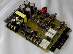
Previously shared RMS 250W auto amplifier JBL filter SMPS EI35 SG3525 project is similar to the PCB design is a very regular auto amplifier circuit. You can use 2x100w rms stereo or 200w rms mono, which can be controlled by bridge connection as well as bass control with cross over circuit with adjustable TL072P op amp at the main entrance floor.
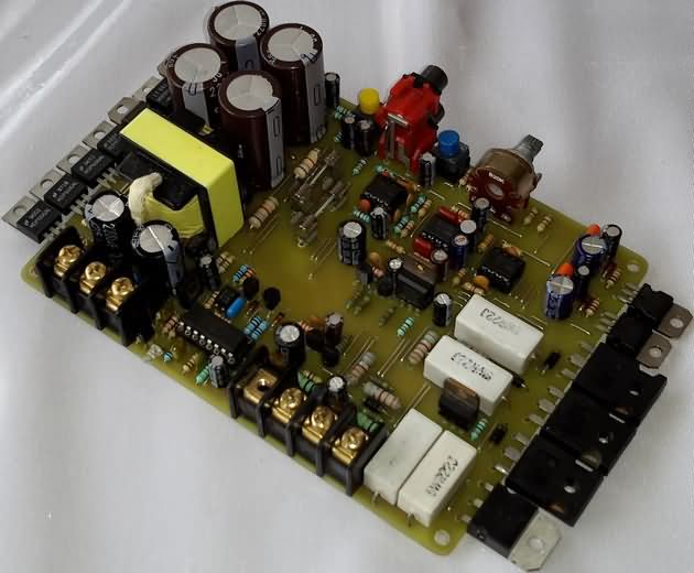
TIP147 TIP142 darlington transistors are used on the power amplifier floor, and BDW83C, BDW84C can be used instead.
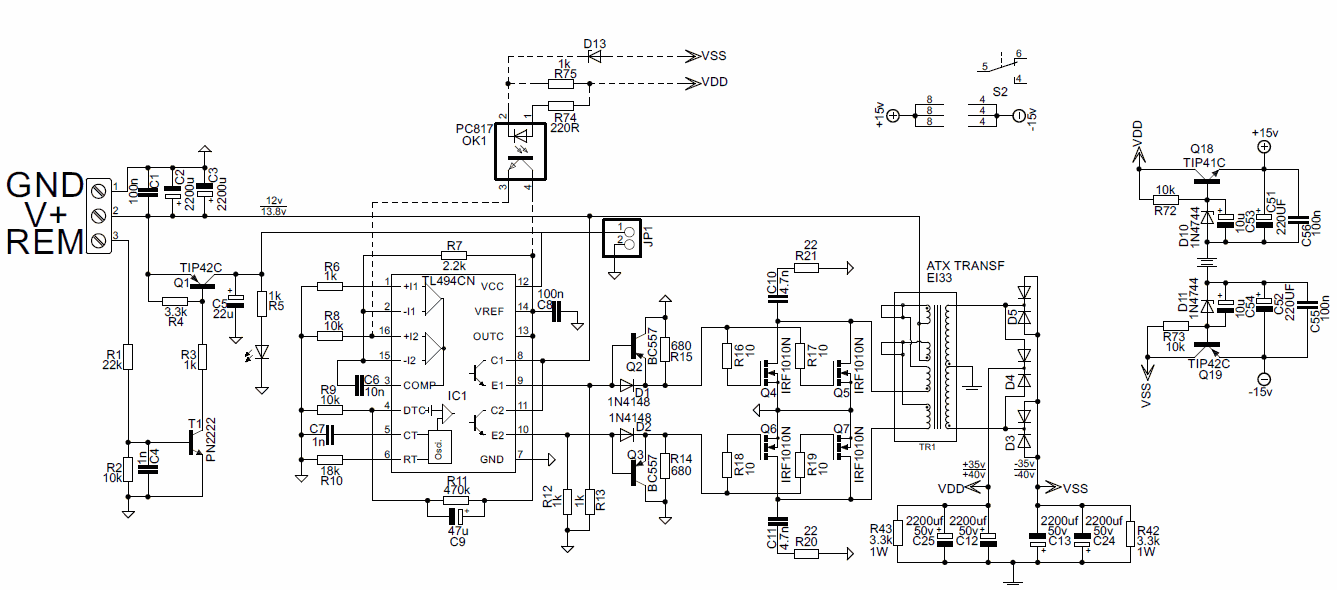
The symmetrical + 35v -35v TL494 DC DC converter circuit required for auto anfin operation is provided. The supply of the cross over circuit is regulated by + -35V TIP41C TIP42C transistors (+ -15V)
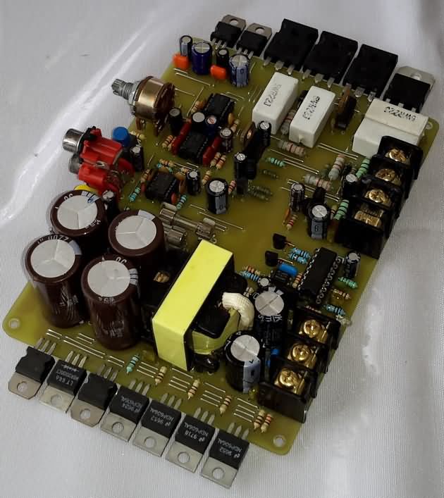
The power core is EI33, AT, ATX power supplies. A lot of articles have been shared about the use of this transformer. In this application, the method of using transformer was made as mentioned in the article of DC DC Converter 200W 2X30V SG3524 SG3525 using EI33 Transformer. The MOSFETs IRF1010N driven at the output of TL494 can be replaced by IRF3205, IRFZ44, 50N06.
The “REM” section on the DC DC power supply circuit with the TL494 PWM control integra- tion. A cable from the ignition wire of the car will be pulled in. This section allows the system to close when the car is not running. You need to give + 12v to your section.
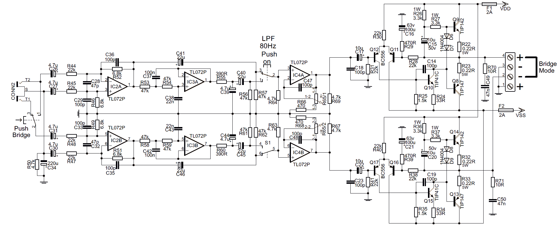
Darlington Amplifier 200W Cross Over Circuit Diagram
Contents
TL494 DC DC Converter Circuit Schematic
200W Auto Amplifier Test
Source: @Alejandro Cesar https://youtu.be/w0edYHMzH4M
FILE DOWNLOAD LINK LIST (in TXT format): LINKS-25946.zip


Auto Verstärker Schaltung TIP142 TIP147 TL494
Früher gemeinsame RMS 250W Auto Verstärker JBL Filter SMPS EI35 SG3525 Projekt ist ähnlich wie die PCB-Design ist eine sehr regelmäßige Auto-Verstärker-Schaltung. Sie können 2x100w RMS Stereo oder 200W RMS Mono verwenden, die sowohl über eine Bridge-Verbindung als auch über eine Bassregelung mit Crossover-Schaltung mit einstellbarem Operationsverstärker TL072P im Haupteingangspegel gesteuert werden können.
TIP147 TIP142-Darlington-Transistoren werden auf dem Endverstärkerboden verwendet, und BDW83C, BDW84C kann stattdessen verwendet werden.
Die symmetrische + 35V-35V TL494 DC-DC-Wandlerschaltung, die für den Auto-Anfn-Betrieb benötigt wird, wird bereitgestellt. Die Versorgung des Cross-Over-Schaltkreises wird von + -35V TIP41C TIP42C Transistoren (+ -15V) geregelt
4 Player Pong Game PIC18f4550
4 Player Pong Game PIC18f4550
The PIC18f4550 microprocessor based pong game PIC18f4550 The first player to reach 20 points in the Pong Game wins the fireworks animation with leds.
The PIC18f4550 works at 8MHz, the display is made up of 900 LEDs arranged in 30×30 size matrise, and besides table preparation, the most demanding part will be 900 strings and soldering.
Game circuit ULN2803 and 74373 integrations are used in the LED driver section. The player selection is controlled by the start buttons.
It is said that the PIC18f4550 game circuit power supply uses 4 pieces of 2500mAh rechargeable battery and it is based on 2 hours of playing every day for half an hour
PIC18f4550 game project software has source code and hex, pcb, gerber files prepared with swordfish basic,
Test video PIC18f4550 game project
Circuit d’amplificateur de voiture TIP142 TIP147 200W DC DC TL494 EI33
Amplificateur automatique RMS 250W précédemment partagé Filtre JBL SMPS EI35 Le projet SG3525 est similaire à la conception PCB est un circuit d’amplificateur automatique très régulier. Vous pouvez utiliser 2x100w rms stéréo ou 200w rms mono, qui peuvent être contrôlés par une connexion en pont ainsi que le contrôle des basses avec circuit croisé avec ampli op TL072P réglable à l’étage d’entrée principal.
Les transistors Darlington TIP147 TIP142 sont utilisés sur le plancher de l’amplificateur de puissance, et les BDW83C, BDW84C peuvent être utilisés à la place.
Le circuit de convertisseur symétrique + 35v -35v TL494 DC DC requis pour le fonctionnement automatique des anfin est fourni. L’alimentation du circuit croisé est régulée par des transistors + -35V TIP41C TIP42C (+ -15V)
Hi
Why you donot use diodz (d13) on your circiut and it not connecte
Hi,
probably works better without feedback
what is the J1 please ?
Hi,
not used. empty as seen in the video.
https://youtu.be/w0edYHMzH4M?t=526
This is a really good amplifier for powering subwoofers. As you know, biasing the Darlingtons is no easy task. This board did a really good job at doing that, but still, at low to medium volumes, you will get distortion, particularly on piano notes. Hence, I first said that this is really good for subwoofers as the bass is really deep (especially if you use NE5532 Op-amps), and you can’t really hear the distortion with subwoofers.
Also, the EI33 is not sufficient for providing enough power for the really power-hungry output section, and it will become saturated at around 120W RMS of output in bridge mode. So that’s why I changed it with a proper toroidal transformer. But if you are using it in stereo mode, the EI33 will suffice.