Temperature measurement is one of the more problematic in electronics. Digital output sensors have a very limited operating range and platinum ones are expensive. Inexpensive silicon sensors may be a solution, but coupling them with a microcontroller is not easy. This arrangement makes them much easier to use. The presented adapter is designed to work with sensors that should be supplied with a current close to 2mA. Such an element is, for example, KTY-84 that can operate at temperatures up to +300°C. The output has a voltage character, which can be easily read with an A/D converter.
The role of the adapter is to supply the sensor with a constant current and non-invasive (currentless) collection of the voltage that builds up on it, along with its possible amplification. It is also possible to adjust the offset, i.e. the temperature at which the output voltage is zero. Since the silicon sensors are of the PTC type, the output voltage will increase in proportion to the temperature.
Schematic diagram of the temperature sensor adapter
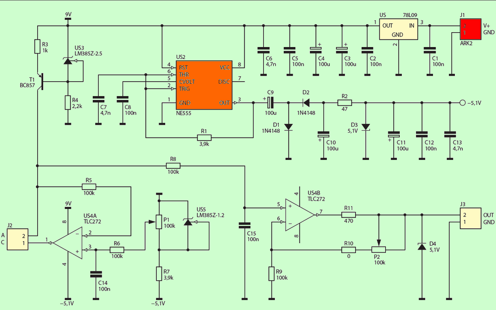
A stable and well-filtered voltage for supplying the remaining components is provided by the US-1 78L09 voltage stabilizer and the C1…C6 capacitors. A DC voltage of 11 V or higher is required for proper operation.
For the correct operation of the input circuits of operational amplifiers, a negative voltage of approx. -5V is generated in the system. A charge pump made on the popular NE555 is used for this. It works in the configuration of an astable generator, producing a square wave signal with a frequency of about 40kHz and a duty cycle close to 50%.
With the help of diodes D1 and D2 and capacitors C9 and C10, a negative voltage is generated, which is stabilized by the zener diode D3 5.1V zenner. Resistor R2 sets the current flowing through it to about 10 mA. The current source circuit was made on the bipolar transistor T1. It is a “push” current source, therefore the polarization of this transistor is of the PNP type.
The US-3 LM385Z circuit ensures that the base of this transistor is at a potential 2.5 volts lower than the positive supply line. This voltage, minus the drop at the base-emitter junction, causes the current flow through the emitter to be about 2 mA. Due to the high current gain, almost the same current flows through the collector.
The US-4A TLC272 operational amplifier and its surrounding components are responsible for the “zero” voltage. The operation of this system is very simple: a voltage source with a very low internal resistance supplies one end of the sensor, and the other end receives the voltage.
Such a source is an operational amplifier working as a voltage follower. The US-5 LM385Z system provides a negative voltage, which can be adjusted with the P1 potentiometer in the range from 0 to -1.25V – this allows you to set the output voltage to zero for a specific temperature.
The voltage deposited on the sensor passes through a very simple RC filter, which removes most of the interference induced in the wires. The US4B operational amplifier works as a non-inverting amplifier, so its input current is negligibly small, maximum 600pA. The P2 potentiometer can be used to adjust the voltage gain in the range from 1 V/V to approx. 2 V/V.
After accidental disconnection of the sensor, the output voltage could reach 9 V, which for many A/D converters is a forbidden value. To avoid this situation, a very simple circuit has been added, consisting of a Zener diode D4 and a resistor R11 470-OHM.
During proper operation, any current drawn by the diode is compensated by the FD loop and it does not affect the operation of the system. In the event of a failure, the op-amp “attempts” to pull the output voltage up to the desired value, but is limited by the zener diode. The operation of the USZ loop forces the amplifier to set the output voltage at the level of 9V, the current flows through it only about 8 mA.
The elements should be assembled starting from surface soldered ones, not forgetting about the wire jumper. It is worth using a stand under the US4 chip, which will facilitate its replacement in the event of possible damage.
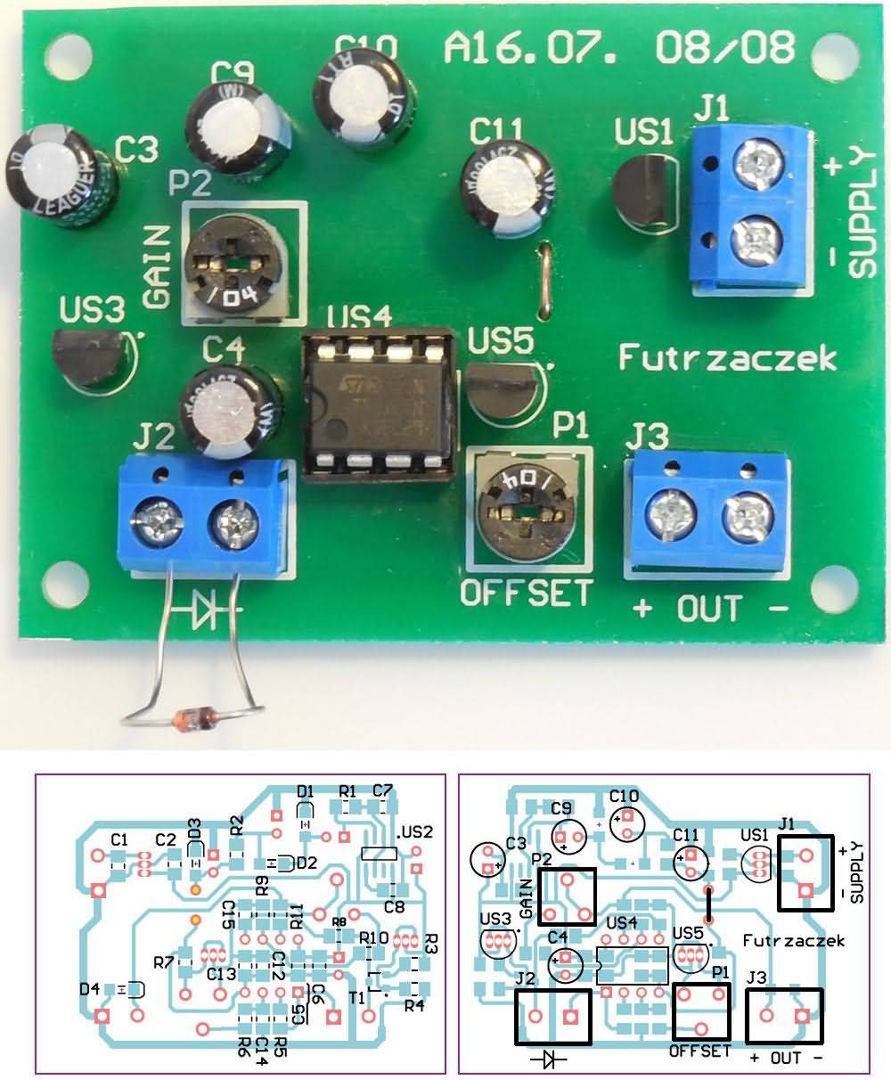
Properly assembled system (with the sensor connected to the J2 terminals) is ready for calibration:
Set the gain to 1 V/V (turn P2 to the right).
Use the P1 potentiometer to adjust the minimum output voltage.
By changing the temperature of the sensor within known limits, set the desired position of P2.
It is worth mentioning that the adjustment with the P1 potentiometer is also able to compensate for the voltage drop on the wires connecting the sensor with the board. The current consumption of the adapter is approx. 27 mA. If the “zero” voltage adjustment is too narrow, you can replace the US5 with a 2.5 V version.
You can also change the diode D4 5.1v zenner if the used A/D converter has a lower range of input voltages, e.g. up to 3.3 V. Finally, it should be added that the adapter does not perform linearization – this should be performed using algorithms based on data from the relevant sensor’s catalog note.
![]()
Altium PCB, part list ALL FILE DOWNLOAD LINK LIST (in TXT format): 26898b.zip pass: 320volt.com


