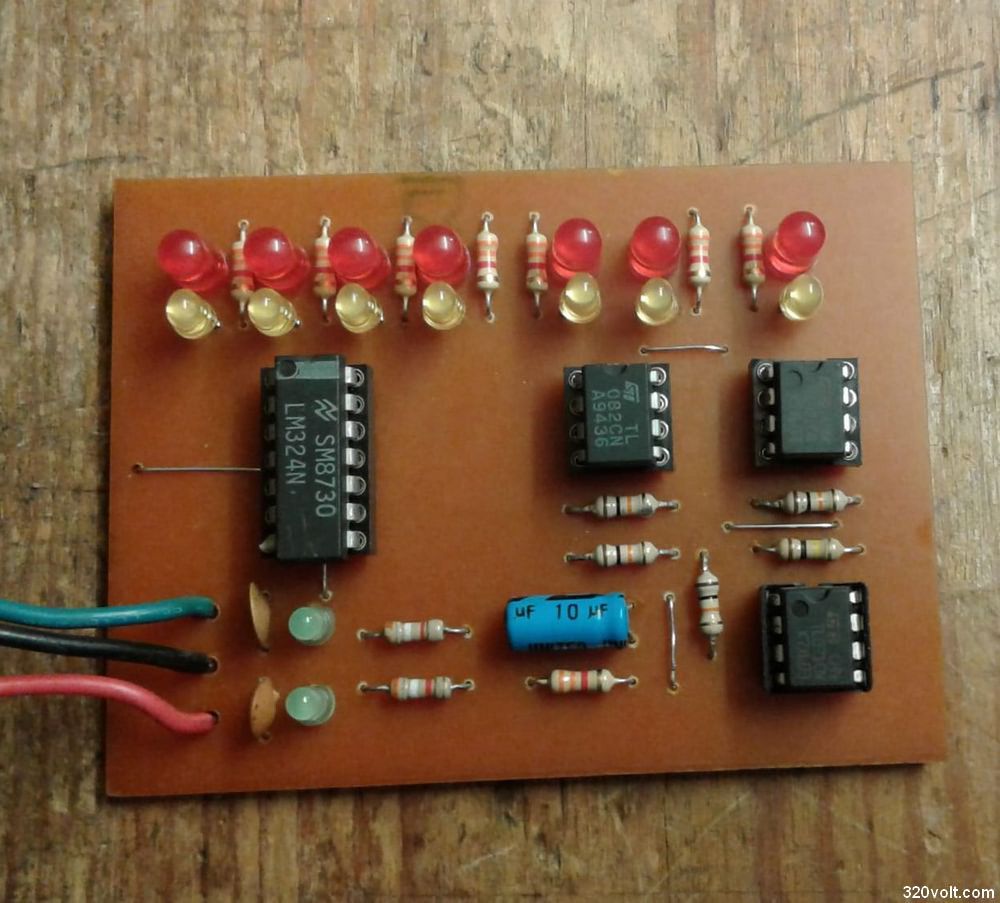
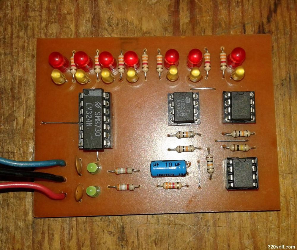
It is actually a simple circuit that makes a flip flop with three different opamp types. The PCB design of the elector is slightly different and the sockets used for testing are assembled using solder.
I made a new PCB drawing that collects all the elements on the mounting face, so we have nothing to do with the PCB drawing of the electron.
Please note that the supply leg connection of the 4 opamp IC is given incorrectly in the circuit diagram. So we wasted a few ICs. Then, I found the correct information in the datasheets of the relevant IC and corrected it in the PCB drawing.
OpAmp Tester Circuit ZIP File Password: 320volt.com


