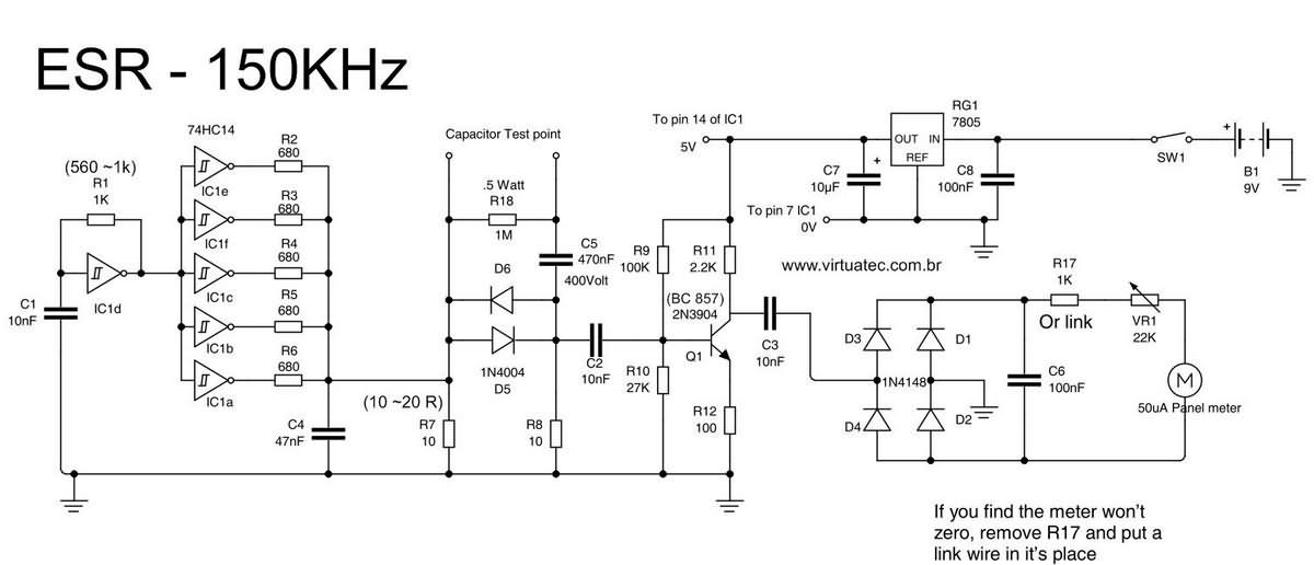
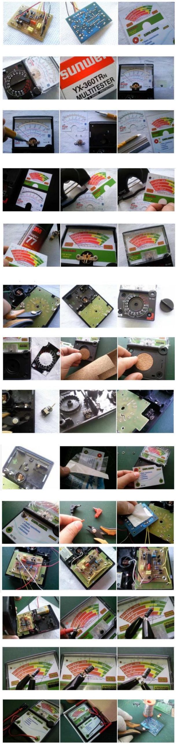
Classic analog ESR meter is a circuit based on SN74HC14N integrated circuit, it mainly consists of 150Khz oscillator, buffer, comparator and rectifier amplifier. The maximum range is approximately 75 Ohms and values below 1 ohm will cause some difficulty in reading the position of the galvanometer pointer due to the area used on the scale being very small, making small values difficult to distinguish.
Some things to consider:
To test if the galvanometer’s springs are bad, short the leads of the device and set it to zero on the scale, then gently tap the side of the multimeter box with your fingers, this will cause the needle to move up and down both sides. it should eventually return to where it was set.
Analog ESR Meter Circuit Diagram
If one of the springs goes late or forward, if it is bad, it causes the weight of the needle to become unbalanced, which starts to change with the external force of the movement we make in the box. The only solution is to replace the galvanometer. In this case, since the quality of these multimeters is very low, it would be good to have a spare moving coil or test it when purchasing.
Sensitivity of the galvanometer (faster ones tend to jolt the needle, and slower ones can give us the impression that the needle has stopped but is still moving)
If there is a displacement with time of use, the capacitor needs to be increased from 100nF to 1uF parallel to the galvanometer (SMD capacitor close to the connecting wires on the board) to balance the speed of the needle movement. Even electrolytic capacitors up to 1uF or 16V can be fixed to the galvanometer terminals, depending on the polarity of the galvanometer.
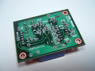
The 150KHz ESR meter board has a 20K multi-turn trimpot (15 turns) in series with the external potentiometer of the multimeter box. One solution to this problem would be to remove the external potentiometer, remove the precision trimpot from the board and fix it. install it in the box instead of the external one and adapt the external button to the trimpot shaft.
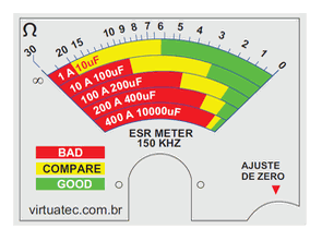
This change in the position of the pointer relative to the numerical scale of the panel is due to the position of the scale when the panel was mounted. Therefore, be very careful when pasting the panel scale label, always paste it aligned on top of the original.
Source: virtuatec-eletronica.blogspot.com
Analog measuring instrument panel, pcb drawings and source files;


Salve, con questo circuito si possono controllare dei condensatori senza essere smontati dalla scheda madre?