
When the DS18B20 Temperature Sensor is transported over long distances, there is a danger of high voltage pulses being transmitted to the cable connecting the sensor to the control unit. If protective measures are not taken, the induced high voltage will lead to degradation of the crystal substrate where the sensor is located. This causes it to heat up and may damage the sensor if the supply voltage is not interrupted.
You can avoid all these problems if you use a simple sensor wiring diagram. This circuit will protect the DS18B20 sensor from high potentials on the power line and bus.
Note in the source article: Based on my experience, I can say that this protection method never fails.
Schematic-1: Sensor protection circuit against high voltage pulses with 5 or 3.3 volt power supply.
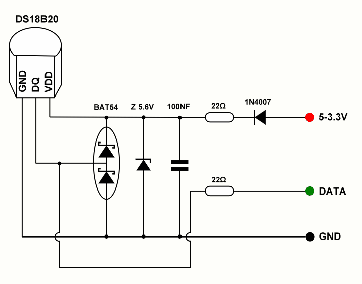
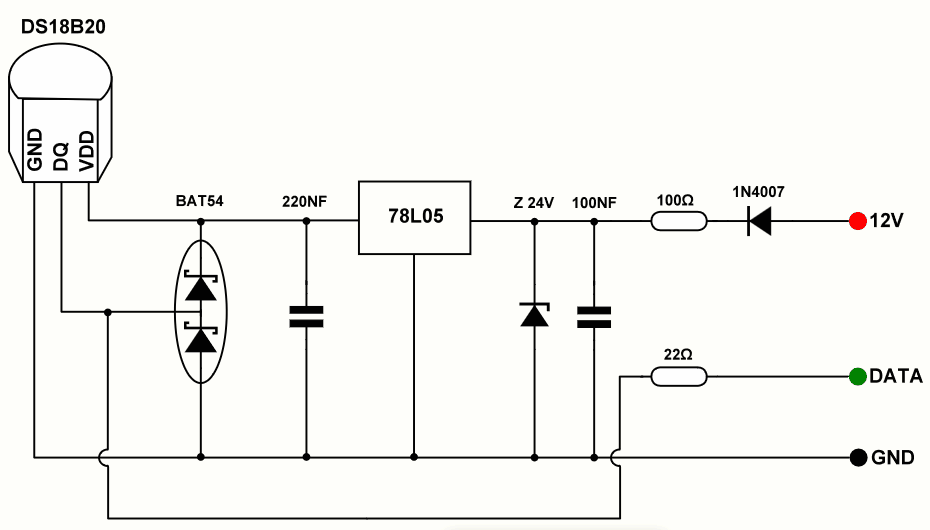
Schottky diodes are added to protect the high voltage bus. Resistors for damping high voltage pulses, Zener diode to limit the supply voltage.
If the DS18B20 supply is to be taken from the MCU power supply, there is no need to use 1N4007 diode.
Schematic-2: Protection circuit of DS18B20 sensor from high voltage pulses with 12 volt power supply.
BAT54=single
BAT54A=dual common anode
BAT54C=dual common cathode
BAT54S=dual serial
Source: catcatcat.d-lan.dp.ua/zashhita-datchikov-temperaturyi-ds18b20-ot-staticheskogo-elektrichestva/


