When implementing control systems, you may encounter many problems of an analog-digital nature. One of these is to detect whether alternating current of a certain intensity passes through a particular cable; This could be a signal that the machine is working properly or vice versa. Current Transformer Module relieves the designer from the burden of designing the analog part because the output of this device operates in zero-one mode.
The purpose of the current detection circuit is to report that a current with a greater amplitude than the set one is flowing in the wire passed through the AMS010 current transformer. It is designed to operate at 50 Hz or 60 Hz mains frequency.
An AMS 010 current transformer is used to measure current. It does not cause losses (like series resistance) and provides very good insulation.
The voltage from the transformer is amplified by two amplifications: with fixed gain of 23 V/V and with adjustable gain in the range 1…51 V/V. They were made on operational amplifiers with TL084 JFET inputs so that the lack of compensation for input currents did not cause a significant shift in the DC component at the output. These stages have AC so that DC from the first does not affect the next.
The frequency response of the amplifier is limited: from the bottom by the time constant C1-R2, C4/R5, C5-R6 and C7/R7, which give a resulting limit frequency of approximately 0.6 Hz, and from the top by R3-C3 and P1-C6. The upper limit frequency depends on the position of P1 and varies between approximately 300 Hz and approximately 700 Hz. Narrowing the bandwidth is necessary to increase stability and reduce the effective noise voltage at the output.
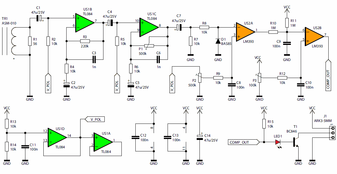
The supply voltage is split in half by the R13/R14 divider, reducing the internal impedance of the source to almost zero WITH the TL084 amplifier. The input of each operational amplifier therefore has a reserve of approximately 6 V from both the lower and upper power lines, which is completely sufficient for the TL084 system. The input of TL084’s unused amplifier to the voltage follower is connected to artificial ground potential.
The amplified voltage signal is placed on resistor R7, which simultaneously polarizes the LM393 comparator input and capacitor C7. Diode D1 shorts the negative halves of the signal and limits the current through resistor R8.
A constant voltage is applied to the second input of the comparator, the value of which is set by potentiometer P2. Pulse height coupling takes place here: each half of the signal whose instantaneous value exceeds the set value resets the comparator output. As long as its amplitude is large enough, it ceases to affect its operation.
The load at the LM393 output is R15 10K resistor. The current supplied by this resistor can flow to the collector of the output transistor in this comparator or to the base of the output transistor T1 through LED1. In the second case, transistor T1 enters saturation (unless the current drawn from it is too high) and a lit LED signals that the output is on.
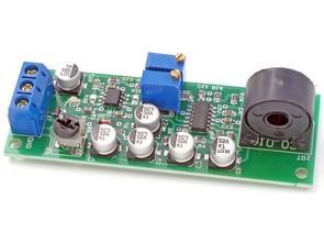
The PCB is mounted on a double-sided printed circuit board with dimensions of 28mm x 78mm. All elements are mounted on the top. A properly assembled board consumes approximately 10 mA when powered by 12V DC. For it to work properly, it needs to be set according to the following steps:
Set potentiometer P1 to highest resistance, P2 to minimum and P3 to maximum.
Once the correct supply voltage is applied to the VCC and GND terminals, LED1 should light up, which is the result of noise amplification. After about 5 seconds, when all capacitors are charged, adjust potentiometer P2 to the position where the LED turns off.
Apply alternating current (at the intensity required to be detected) through a wire passed through the hole in the transformer. If LED1 is on, adjust potentiometer P2 to find the setting at which the LED turns off after a slight movement.
If such a position cannot be found, reduce the gain with potentiometer P1 and adjust P2 again. The desired effect is for the LED to turn on continuously (not blink) when the current is turned on and then turn off immediately.
The P3 potentiometer allows you to adjust the switching threshold of the final comparator and therefore the turn-off delay time. When you turn the potentiometer towards MIN, the delay in turning off the LED after the flow disappears will decrease, but the response time to the appearance of current will increase. The position of this potentiometer can be selected depending on which moment (on or off) is more important. After setting all the potentiometers correctly, the current detector is ready for operation.
![]()


