There are a lot of different soldering stations on the Internet, but everyone has their own characteristics. Some are difficult for beginners, others work with rare soldering irons, some are not finished, etc. We focused on simplicity, low cost and functionality, so that every beginner radio amateur could assemble such a soldering station.
A regular soldering iron that is directly connected to the network simply heats constantly with the same power. Because of this, it heats up for a very long time and there is no way to regulate the temperature in it. You can dim this power, but it will be very difficult to achieve a stable temperature and repeatability of soldering. A soldering iron prepared for the soldering station has a built-in temperature sensor and this allows for maximum power to be supplied to it during heating and then to keep the temperature at the sensor.
If you simply try to adjust the power in proportion to the temperature difference, it will either warm up very slowly or the temperature will float cyclically. As a result, the control program must contain the PID control algorithm. In our soldering station, of course, we used a special soldering iron and paid maximum attention to temperature stability.
Soldering Station Circuit Specifications
Contents
Powered by a DC voltage source of 12-24V
Power consumption, with 24V power: 50W
Soldering iron resistance: 12Ω
Time of an exit to an operating mode: 1-2 minutes depending on the feeding tension
Maximum deviation of temperature in the stabilization mode, not more than 5 degrees
Regulation algorithm: PID
Display of temperature on a seven-segment display
Heater type: nichrome
Type of temperature sensor: thermocouple
Temperature calibration capability
Setting the temperature with the help of an ecooder
LED to display the status of the soldering iron (heating / work)
Soldering Station Circuit Schematic diagram
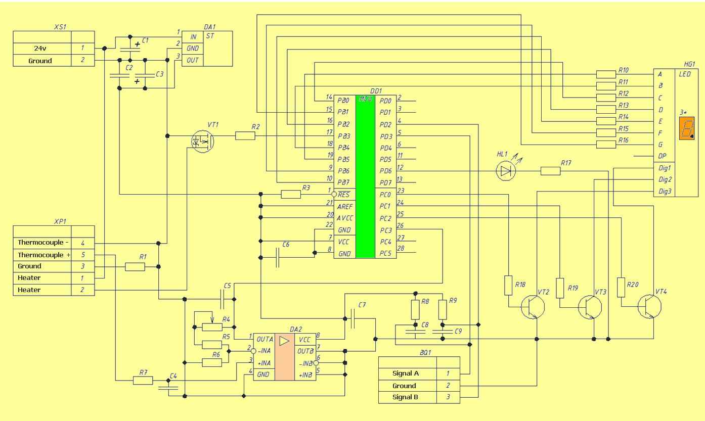
The scheme is extremely simple. At the heart of the whole microcontroller Atmega8. The signal from the optocoupler is fed to the LM358 operational amplifier with an adjustable gain (for calibration) and then to the input of the ATmega8A microcontroller’s ADC. To display the temperature, a seven-segment indicator with a common cathode is used, the discharges of which are included through transistors. When the knob of the BQ1 encoder is turned, the temperature is set, and the rest of the time the current temperature is displayed. When enabled, the initial value is set to 280 degrees. Determining the difference between the current and the required temperature, recalculating the coefficients of the PID components, the microcontroller with the help of PWM modulation heats the soldering iron. To power the logical part of the scheme, a simple linear stabilizer DA1 to 5V was used.
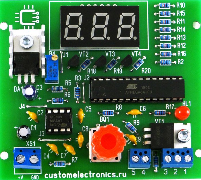
Component List
The following components and materials are required to assemble the circuit board and case:
BQ1. Encoder EC12E24204A8
C1. Electrolytic capacitor 35V, 10µF
C2, C4-C9. Ceramic capacitors X7R, 0.1µF, 10%, 50V
C3. Electrolytic capacitor 10V, 47µF
DD1. ATmega8A-PU microcontroller in DIP-28 package
DA1. Voltage Stabilizer L7805CV to 5V in TO-220 package
DA2. Operational amplifier LM358DT in DIP-8 package
HG1. Seven-segment three-digit indicator with a common cathode BC56-12GWA. Also, the board provides a seat for a cheap analogue.
HL1. Any indicator LED for a current of 20mA with a terminal pitch of 2.54 mm
R2, R7. Resistors 300 Ohm, 0.125W - 2pcs
R6, R8-R20. Resistors 1KΩ, 0.125W - 13pcs
R3. 10kΩ resistor, 0.125W
R5. 100kΩ resistor, 0.125W
R1. Resistor 1Ω, 0.125W
R4. Trimmer resistor 3296W 100kΩ
VT1. Field-effect transistor IRF3205PBF in TO-220 package
VT2-VT4. BC547BTA Transistors in TO-92 package - 3pcs
Xs1. Two-prong terminal with lead pitch 5.08 mm
Two-prong terminal with lead pitch 3.81mm
Three-prong terminal with lead pitch 3.81mm
Radiator for stabilizer FK301
DIP-28 body block
DIP-8 body block
Connector for soldering iron
Power Switch SWR-45 B-W (13-KN1-1)
Soldering iron. We will write about it later
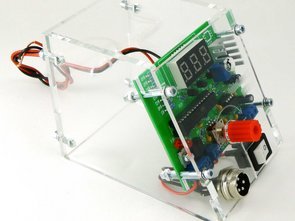
Details from plexiglas for the body (files for cutting at the end of the article)
Encoder knob. You can buy it, or you can print it on a 3D printer. File for downloading the model at the end of the article
Screw M3x10 - 2pcs
Screw M3x14 - 4pcs
Screw M3x30 - 4pcs
M3 nut - 2pcs
Nut M3 square - 8pcs
M3 washer - 8pcs
M3 horizontal washer - 8pcs
Also required for the assembly of assembly wires, ties and shrink tube
Details of the installation process will be shown and commented in the video below. We note only a few points. Observe the polarity of the electrolytic capacitors, the LED and the installation direction of the microcircuits. Chips are not installed until the casing is fully assembled and the supply voltage is not checked. Chips and transistors must be handled with care so as not to damage them with static electricity.
That is, it remains only to bring power to the board and connect the soldering iron connector.
The soldering iron connector requires soldering five wires. To the first and fifth red, to the rest black. Contact must immediately put on a heat shrink tube, and tin the loose ends of the wires.
Short (from switch to board) and long (from switch to power supply) red wires should be soldered to the power switch. Then the switch and the connector can be installed on the front panel. Please note that the switch may be very tight. If necessary, modify the front panel files!
ATmega8 Microcontroller firmware and setup
You can find the HEX file for the controller firmware at the end of the article. The fusion bits should remain factory-set, that is, the controller will operate at 1 MHz from the internal oscillator.
The first switching on should be done before installing the ATmega8 microcontroller and the operational amplifier on the board. Apply a constant supply voltage from 12 to 24V (red should be “+”, black “-“) to the circuit and check that there is a 5V supply voltage between the terminals 2 and 3 of the stabilizer DA1 (middle and right terminals). After that, turn off the power and install the chips DA1 and DD1 in the panels. At the same time watch the position of the key chips.
Turn on the soldering station again and make sure all functions work correctly. The indicator displays the temperature, the encoder changes it, the soldering iron heats up, and the LED signals the operating mode. Next, you need to calibrate the soldering station. The best option for calibration is the use of an additional thermocouple. It is necessary to set the required temperature and check it on the sting by the reference device. If the readings differ, adjust the multi-turn trimmer resistor R4. When setting up, remember that the indicator readings may differ slightly from the actual temperature. That is, if you set, for example, the temperature is “280”, and the indicator readings are slightly deviated, then according to the reference instrument you need to achieve exactly the temperature of 280 ° C. If you do not have a test measuring device at hand, you can set a resistor of about 90kΩ and then select the temperature by experiment. After the soldering station is checked, you can carefully, so as not to crack the details, install the front panel.
In the current version, we updated the drawings for cutting Plexiglas, making PCBs, and also updated the firmware to remove the flickering indicator. Please note that for the new firmware version you need to enable CKSEL0, CKSEL2, CKSEL3, SUT0, BOOTSZ0, BOOTSZ1 and SPIEN (that is, change the default settings).
Source: customelectronics.ru/simple_solder_mk936
FILE DOWNLOAD LINK LIST (in TXT format): LINKS-26215.zip


Phone Ring Amplifier Circuit
Phone Ring Amplifier Circuit
Phone Ring Amplifier Circuit People with hearing problems do not hear a phone call or intercom. Often the reason is the low volume of the bell built into the device. This project can eliminate this problem. This project is not an amplifier in the literal sense. Rather, it can be called a sound comparator, which detects exceeding the set signal intensity, and then emits its own, much more powerful. The sensor detecting sounds is the MIC1 electret microphone.
For proper operation it requires DC power supply, which is ensured by the R1 resistor. The constant component is then separated by the C1 capacitor, and the variable component (low amplitude) goes to the input of the inverting amplifier. To avoid using it with symmetric voltage, a “trick” was used to place its non-inverting input on a potential equal to half of UZAS, amounting to approx. 6 V. Due to this move, implemented on R2 and R3 resistors, it seems to be powered symmetrically ± 6 V. C2 capacitor filters the artificial ground voltage, resistor R4 sets the gain.
The amplified signal (together with a constant component of approx. 6 V) goes to the second operational amplifier operating as a voltage comparator. If the temporary voltage level at its non-inverting input falls below the level set by potentiometer P1, then it causes the output voltage close to 0. This in turn triggers the monostable multivibrator (US2 ne555 system) for five seconds, thus supplying the US3 cd4093 system containing four NAND Schmitt gates.
Phone Ring Amplifier Circuit Schematic
Circuit de station de soudage maison bricolage simple MK936 Circuit
Il existe de nombreuses stations de soudage différentes sur Internet, mais chacun a ses propres caractéristiques. Certains sont difficiles pour les débutants, d’autres fonctionnent avec des fers à souder rares, certains ne sont pas finis, etc. Nous nous sommes concentrés sur la simplicité, le faible coût et la fonctionnalité, afin que chaque radio-amateur débutant puisse assembler une telle station de soudage.