One of the most important problems in electrode heater systems is that the current drawn also increases as the liquid temperature rises. The system, which starts operating with low current at first, may draw more current as heating progresses. After a certain point, this situation can lead to problems such as boiling sounds, irregular operation, a decrease in liquid level, and reduced efficiency.
For the electrode heater, current limiting was applied with a PIC12F675-based circuit, making the electrode heater more stable.
The electrode heater current stabilization circuit with PIC12F675 offers a very practical solution in this type of system, which is difficult to control with classic methods.
The main purpose is not to completely reduce the power, but to keep the current within a safe and efficient range. In this way, both heating performance is preserved and the system becomes quieter, more stable, and requires less maintenance.
This approach provides significant advantages especially in applications where the electrode surface changes over time, the liquid concentration does not remain constant, and the current naturally increases.
With proper assembly and correct calibration, efficient current control can be achieved in electrode heater systems.
What Is an Electrode Heater?
Contents
- 1 What Is an Electrode Heater?
- 2 Why Is Current Stabilization Required in Electrode Heaters?
- 3 Solution: Period Skipping Method Instead of Phase Control
- 4 Operating Principle of the Circuit with PIC12F675
- 5 Main Components Used in the Circuit
- 6 How Was the Current Sensor (Current Transformer) Made?
- 7 How Was the Magnetic Core Prepared?
- 8 How Was the Primary Side Created?
- 9 How Is the Current Threshold Adjusted?
- 10 Why Does the LED Blink?
- 11 Advantage of This Current Transformer Structure
- 12 Advantages Provided by This Circuit
An electrode heater is a special system that operates differently from classic resistance-type electric heaters. In this structure, heat is generated not through a resistance wire, but by passing alternating current through water or a liquid that has been given conductive properties. In other words, the electrical resistance of the liquid is used directly in heat generation.
Therefore, the operating character of the system may vary depending on the conductivity, temperature, concentration, and electrode surface condition of the liquid.
Although in some applications a body similar to a radiator or panel radiator may be used in terms of appearance, its operating principle is different from classic electric radiators.
In classic type devices, the main element that produces heat is the heating resistance, while in electrode systems, heat is generated directly inside the liquid medium.
Why Is Current Stabilization Required in Electrode Heaters?
In this type of heater, the current drawn when the system is cold may remain at a low level.
However, as the temperature rises, the current increases, and after a certain point, boiling, knocking, crackling, and irregular operation may be seen inside the heater.
As the liquid decreases or the structure of the solution changes, the system becomes even more unstable.
In practical use, it has been observed that a level of approximately 2.5A both provides sufficient heating and allows the system to operate more quietly and more evenly.
However, it is not easy to keep this current constant only by adjusting the liquid concentration.
Due to the electrodes corroding over time, the contact surface changing, and the properties of the solution becoming different, the current value does not remain constant.
For this reason, an electronic current limiting and stabilization circuit becomes necessary.
Solution: Period Skipping Method Instead of Phase Control
In this project, instead of classic phase control, the period skipping technique, which is a cleaner and more efficient method in practice, is used.
In this method, within a certain time interval, some full waves of the mains signal are transferred to the load, while some are intentionally skipped.
In this way, the average current is reduced and brought closer to the target level.
Since switching on occurs near the zero crossing of the voltage and switching off occurs near the point where the current becomes zero, the interference given to the mains remains quite low.
Especially in systems with high thermal inertia, that is, in applications where temperature change progresses slowly, this method gives quite successful results.
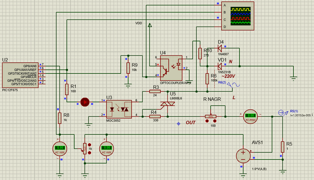
Operating Principle of the Circuit with PIC12F675
At the center of the circuit is the PIC12F675 microcontroller. The microcontroller monitors the mains half-waves from the input pin.
When a positive half-wave is detected, the control algorithm is activated and the load current is compared with the calculated threshold value.
If the average current rises above the defined limit, the software reduces power by skipping more periods.
When the current drops below the target value, the number of skipped periods is reduced. In this way, the system operates by continuously establishing balance around the defined current threshold.
This method is effective because the resistance of the liquid inside the electrode heater does not change very rapidly instantaneously.
Since the heating process has a certain inertia, the microcontroller keeps the average current balanced and allows the system to operate more stably.
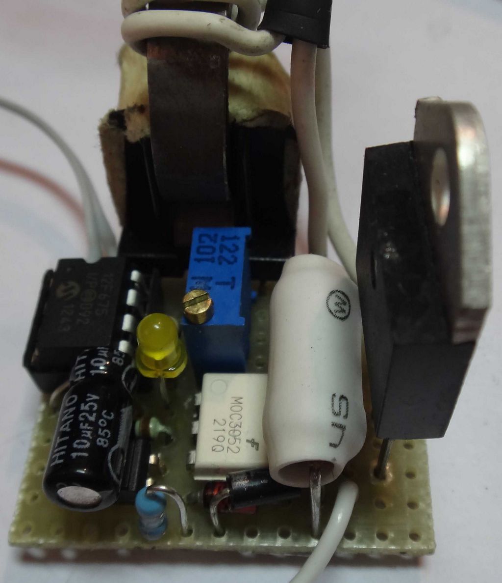
Main Components Used in the Circuit
- PIC12F675 microcontroller
- Optotriac driver (MOC series)
- Triac
- 12V power supply structure
- Handmade current transformer for current sensing
- RV1 trimpot for threshold adjustment
- LED as status indicator
The control circuit can be designed isolated from the mains. However, depending on the application, a transformerless power supply solution may also be preferred.
On the triac side, a component with a suitable current rating should be selected according to the load power, and a heatsink should be used if necessary.
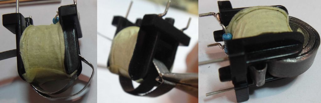
How Was the Current Sensor (Current Transformer) Made?
In this project, a ready-made sensor module was not used for current sensing; instead, a completely handmade current transformer was prepared.
Because ready-made sensors are costly and the same circuit is needed for more than one device, a more economical and practical method was applied.
The purpose here is not to perform high-precision laboratory measurement, but to detect a certain current threshold and provide feedback to the control circuit.
As the bobbin of the current transformer, a UU10.5XXX series bobbin and plastic body belonging to an old mains EMI filter were used.
The separator section on the bobbin was cut and removed, and then the surface was smoothed with a file.
On this prepared bobbin, approximately 2000 turns were wound with 0.1 mm wire, and the winding output was shunted with a 1 kOhm resistor.
In this way, the signal received from the sensor was brought to a suitable level that the control circuit could process.
How Was the Magnetic Core Prepared?
A ready-made toroidal core was not used as the magnetic core; instead, the magnetic sheet strip removed from an old toroidal transformer was used.
This sheet was cut into strips approximately 50 cm long with metal shears so that it would fit the window width, and then burrs and irregularities on the edges were lightly filed.
Thus, the sheet was made to pass easily through the bobbin.


Then the sheet strip was wound around the bobbin in layers, completing the magnetic section. After approximately 7-8 layers of winding, a usable AC current transformer was obtained.
Since the inner part of the bobbin was flat, the sheet strip was placed by bending it approximately 90 degrees during winding.
The result was not a perfectly round toroid, but a core shape with a flat base and an arch-like form. However, since the purpose in this application is not precision measurement but threshold detection, this structure was considered sufficient.
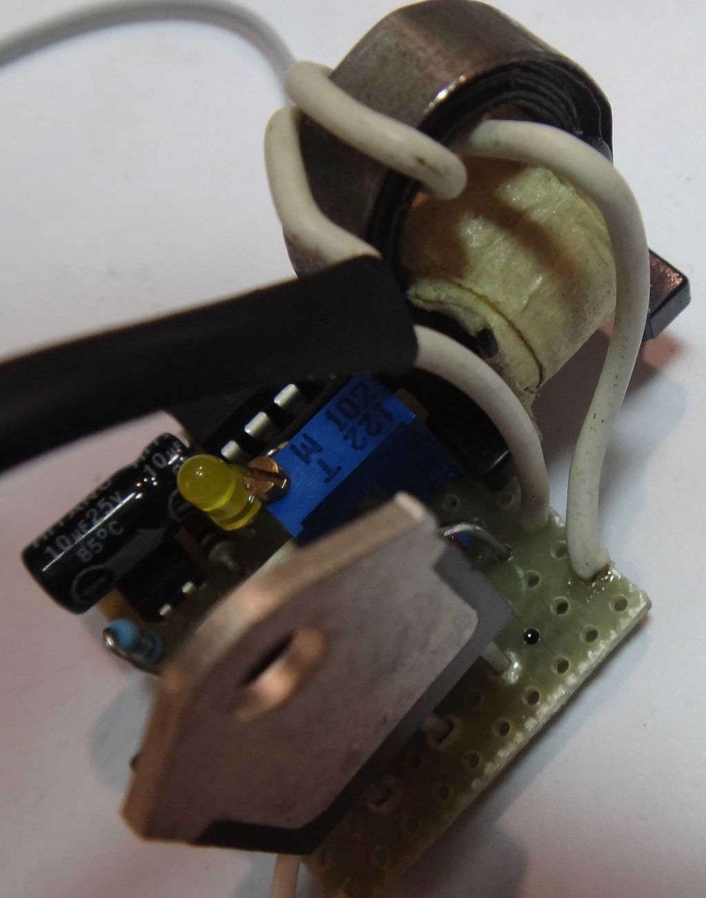
How Was the Primary Side Created?
There is no separate primary winding in this current transformer. Instead, the cable going from the triac to the load was passed 2 turns through the magnetic core.
Thus, the load current directly acts as the primary. This method both simplifies the structure and eliminates the need for an additional thick primary winding.
One of the important points here is the passing direction of these two turns. Because the signal received from the sensor is processed in the circuit according to a specific half-wave condition.
If the direction of the primary line passing through the core is selected in reverse, the sensing logic may be disrupted or the threshold point may operate incorrectly. Therefore, the direction in which the cable passes through the core should not be chosen randomly.
How Is the Current Threshold Adjusted?
This sensor is not used like a precision measuring device; it is used to reference a certain current value. The RV1 trimpot in the circuit is used to adjust the signal level coming from the current transformer.
The purpose is to ensure that the processed form of the sensor output corresponds to the threshold value defined in the software at the ADC input of the microcontroller.
The calibration process is quite practical. An ammeter is connected in series with the load, and then the RV1 trimpot is slowly turned to bring the system to the desired current level.
In practice, this value was adjusted to approximately 2.5A. When the trimpot reaches the correct point, the system switches to current stabilization mode.
Why Does the LED Blink?
The LED in the circuit does not only show that power is present. It also indicates that the system is performing current stabilization.
The blinking of the LED means that the microcontroller skips some AC periods in order to keep the average current at the defined level.
The more frequently the LED blinks, the more waves the system is skipping. This indicates that the average current is being limited more.
Advantage of This Current Transformer Structure
This type of handmade current transformer is quite useful in circuits that do not require industrial precision but operate for threshold detection, current limiting, and protection purposes.
It is low-cost, easy to produce, and adjustable in the field.
In systems such as electrode heaters, where the load character changes according to temperature and operating conditions, it can be used as a practical and effective feedback element to keep the current under control.
Advantages Provided by This Circuit
- Limits excessive current rise in electrode heaters
- Reduces boiling, knocking, and irregular operation problems
- Helps slow down liquid loss
- Creates lower mains interference compared to phase control
- Can be easily operated with correct assembly thanks to its simple structure
- Provides more balanced heating in long-term use
WARNING Since this circuit operates in a structure directly related to the mains, electrical safety must be kept at the forefront during assembly and testing. The circuit operates with high voltage. Be careful, pay attention to capacitor connections. If you connect the + – polarities in reverse, large explosions may occur at high voltage. Before operating the circuit, use a Fused Electrical Line and protective glasses.
There are source .asm, .hex, .cof files belonging to the project, as well as Proteus simulation and Sprint Layout PCB drawing files.
Source: chipmk.ru (closed)