Phone Ring Amplifier Circuit People with hearing problems do not hear a phone call or intercom. Often the reason is the low volume of the bell built into the device. This project can eliminate this problem. This project is not an amplifier in the literal sense. Rather, it can be called a sound comparator, which detects exceeding the set signal intensity, and then emits its own, much more powerful. The sensor detecting sounds is the MIC1 electret microphone.
For proper operation it requires DC power supply, which is ensured by the R1 resistor. The constant component is then separated by the C1 capacitor, and the variable component (low amplitude) goes to the input of the inverting amplifier. To avoid using it with symmetric voltage, a “trick” was used to place its non-inverting input on a potential equal to half of UZAS, amounting to approx. 6 V. Due to this move, implemented on R2 and R3 resistors, it seems to be powered symmetrically ± 6 V. C2 capacitor filters the artificial ground voltage, resistor R4 sets the gain.
The amplified signal (together with a constant component of approx. 6 V) goes to the second operational amplifier operating as a voltage comparator. If the temporary voltage level at its non-inverting input falls below the level set by potentiometer P1, then it causes the output voltage close to 0. This in turn triggers the monostable multivibrator (US2 ne555 system) for five seconds, thus supplying the US3 cd4093 system containing four NAND Schmitt gates.
Phone Ring Amplifier Circuit Schematic
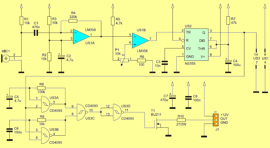
Two of them generate rectangular waveforms with an approximate 50% fill: US3A cd4093 with a frequency of 0.5 Hz, US3B with a frequency of 150 Hz. The US3C gateway performs the multiplication of logical values represented by both signals, as a result of which an intermittent tone is obtained at its output. The gate of transistor T1 buz11 is connected directly to the output of the US3D cd4093. Resistor R10 connected in series with a T1 drain limits the output power by reducing the current amplitude in this circuit.
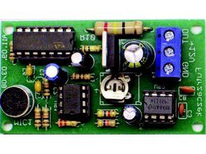
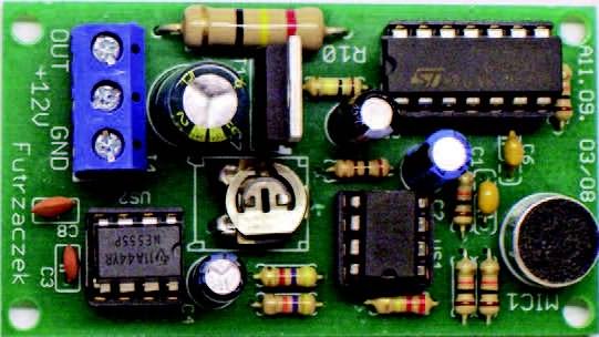
The device was assembled on a plate with dimensions of approx. 65 mm × 38 mm, the assembly diagram of which is shown in figure 2. Under the integrated circuits, it is worth to use stands. The microphone should be soldered in such a way that its housing is compact with the ground.
Between the OUT a + 12V output of the J1 connector, a wideband loudspeaker with a coil impedance of 4 … 8 Ω and a nominal power of several watts should be switched on. It should be moved away so that it does not affect the microphone. The microphone should be positioned as close as possible to the bell speaker. The current consumption at rest is approx. 10 mA, and during sound emission it increases to approx. 80 mA (mean value).
![]()
FILE DOWNLOAD LINK LIST (in TXT format): LINKS-26207.zip


Simple DIY homemade soldering station MK936 Circuit
Simple DIY homemade soldering station MK936 Circuit
There are a lot of different soldering stations on the Internet, but everyone has their own characteristics. Some are difficult for beginners, others work with rare soldering irons, some are not finished, etc. We focused on simplicity, low cost and functionality, so that every beginner radio amateur could assemble such a soldering station.
A regular soldering iron that is directly connected to the network simply heats constantly with the same power. Because of this, it heats up for a very long time and there is no way to regulate the temperature in it. You can dim this power, but it will be very difficult to achieve a stable temperature and repeatability of soldering. A soldering iron prepared for the soldering station has a built-in temperature sensor and this allows for maximum power to be supplied to it during heating and then to keep the temperature at the sensor.
If you simply try to adjust the power in proportion to the temperature difference, it will either warm up very slowly or the temperature will float cyclically. As a result, the control program must contain the PID control algorithm. In our soldering station, of course, we used a special soldering iron and paid maximum attention to temperature stability.
Circuit d’amplificateur de sonnerie de téléphone
Circuit d’amplification de la sonnerie du téléphone Les personnes ayant des problèmes d’audition n’entendent ni appel ni interphone. La raison en est souvent le faible volume de la cloche intégrée à l’appareil. Ce projet peut éliminer ce problème. Ce projet n’est pas un amplificateur au sens littéral. Au contraire, il peut être appelé un comparateur de sons, qui détecte le dépassement de l’intensité du signal défini, puis émet le sien, beaucoup plus puissant. Le capteur détectant les sons est le microphone à électret MIC1.