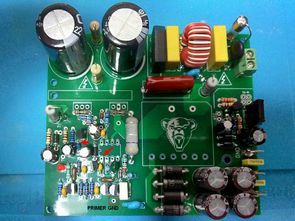
12V 20A Lead-Acid Battery Charger TL494 UC2906 ACS758
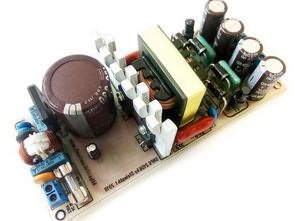
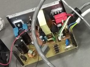
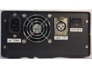
The designed SMPS charger system uses both constant current and constant voltage charging methods. It can be used to charge classic, gel and traction accumulators with a working voltage of..
SMPS Circuits, SMPS Projects SMPS stands out, Switch Mode Power Supply There are basically 3 types of buck converter, boost converter and lowering-amplifier converter.
The designed SMPS charger system uses both constant current and constant voltage charging methods. It can be used to charge classic, gel and traction accumulators with a working voltage of..
An SMPS switched power supply project for power amplifiers with the IR2156 half-bridge mosfet driver IC from International Rectifier (currently acquired by Infineon Technologies). Brief information about IR 2156. The..
1200W 60V SMPS Power supply UC3844 Classic topologies of blocking converters are usually considered suitable only for small ones performance, on the order of about 100-200 W. Their main advantage..
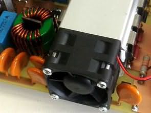
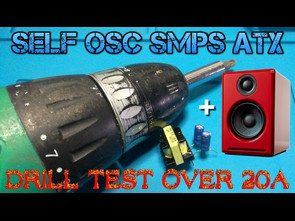
Simple SMPS Circuit Self-Oscillating ATX Transformer There were shares to run the rechargeable drill without a battery IR2153 SMPS, Battery, Transformer.. The batteries of the drill I used were also..
2X84V 2X35V 14V 220W 300W 1000W SMPS circuits based on the SG3525 PWM control IC have been designed with a 14v output of the 300W output, and the SG3525 current..
I shared many SMPS circuits made with IR2153. IR2153 is especially suitable for use in amplifier power supplies, even in power amplifiers in large companies, in mixers Power supply uses..
The 0.2V-80V switched power supply built on TL494 Integration can be used in various devices, motors, battery, battery charging processes, etc. designed for. There is additional SMPS circuit with TNY267..
SMPS designs designed as IR2153 amplifier power source based on IR2153 Integration. The 300W version gives 2X44V DC. Circuits have Short circuit protection. IR2153 SMPS 300W Version: In general, IR2153..
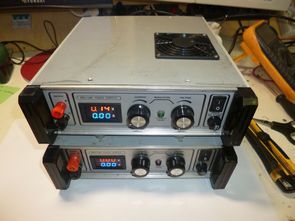
SG3525 Adjustable SMPS 0-30V 0-5A Laboratory Switching Power Supply The SG3525A circuit was selected as the PWM modulator for controlling the switching power supply. It is a PWM modulator specially..
UC3845 LiFePO4 switch mode power supply charger. In order to simplify the connection, reduce the number of components and reduce the expected sources of problems, the following sections have been..