1200W 60V SMPS Power supply UC3844 Classic topologies of blocking converters are usually considered suitable only for small ones performance, on the order of about 100-200 W. Their main advantage for low-power applications is simplicity and large input voltage range. At the output of the transformer only the rectifier diode and the output capacitor are connected. Unlike permeable transducers it is not necessary to use a large external choke, because from the principle of function it is the choke itself transformer. Only a small choke of the eventual smoothing LC member is sufficient.
The following parameters were determined for the constructed experimental SMPS converter:
- SMPS Output power: = 1200W
- SMPS Output voltage: = 60V
- SMPS Output current: = 20A
- SMPS Switching frequency: fPWM = 150kHz
- Power supply from a single-phase network 230V
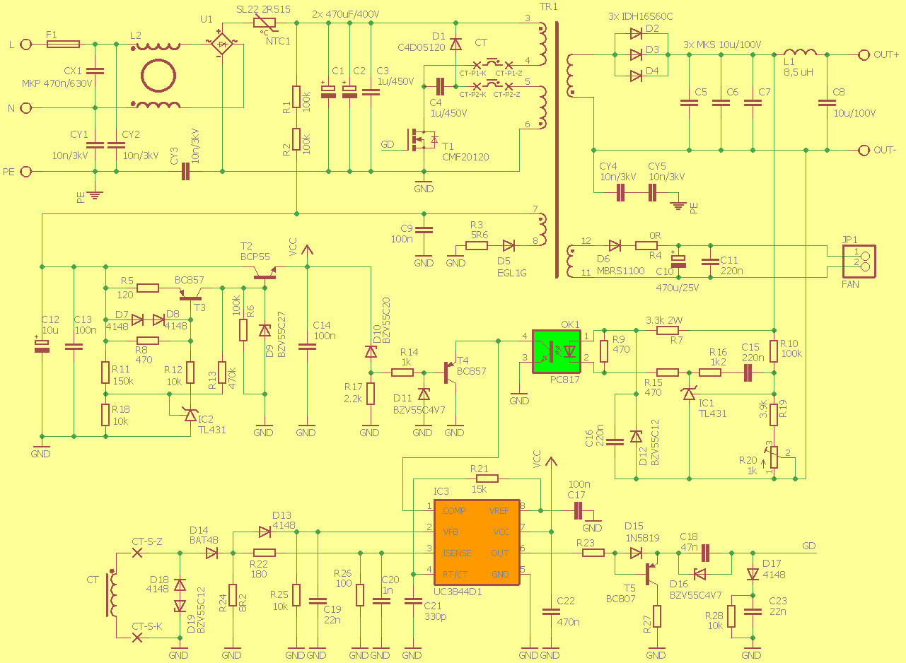
1200W 60V SMPS Circuit Schematic Diagram
After installing the steering components, we verified the controller’s function when powered from an external source circuit and excitation of the transistor, which worked correctly after fine-tuning the switching frequency.
Also the function of the voltage stabilizer and the starting circuit was tested. The starting circuit switches at reaching a voltage of 40 V and switches off when the voltage drops below 32 V, which corresponds to the designed I value.
Subsequently, we connected the supply voltage to the input of the inverter through the regulating autotransformer. First, we set the control circuits with an external power supply and with a small resistive load small input voltage.
It is necessary to connect the load, since in the case of a non-functioning regulator it would be without load of the output, the output voltage could increase uncontrollably in contrast to the pass-through ones sources where its size is practically limited by the height of the voltage pulse.
We are in this state they checked the voltage curve on the transistor, the excitation operation and the presence of pulses on the shunt current transformer. By further increasing the input voltage, it reached the output voltage set value of 60V and it was possible to verify the functionality of the regulator on the secondary side of the inverter which limited the size of the pulses and the output voltage reached the required value. By increasing the output load and input voltage, we achieved a larger current.
![]()
FILE DOWNLOAD LINK LIST (in TXT format or file): 26765b.zip pass: 320volt.com


Hy My name is Sagheer Ahmad From Pakistan.I like this Project. I need a High Voltage Power Supply. So Please share Resistor Value R23 or R27 Or Transformer Winding Data. i want to make this supply a turn any fixed voltage variable power supply.
‘please Reply my Question