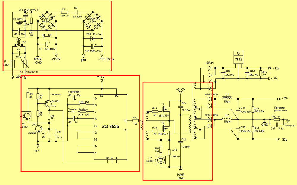
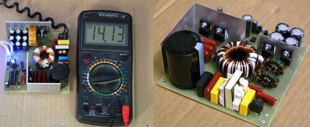
2X84V 2X35V 14V 220W 300W 1000W SMPS circuits based on the SG3525 PWM control IC have been designed with a 14v output of the 300W output, and the SG3525 current limiting circuit is also shared for battery charging. The design of the circuits is tidy in the simple PCB drawings, but the PC40 toroidal ferrite core is used for the mosfet version and the power transformer. PC40 is produced in different sizes. Different toroidal cores can be tried according to the dimensions given for the driver and power transformer. For SMPS Transformer calculation, previously shared SMPS Converter Coil Transformer Calculation Programs were used. The operating frequency of the circuits is 50kHz.
There are no major changes in SMPS circuit diagrams. There are additional diodes, regulators and changes in the winding of the output power transformer according to the power and additional outputs.
Toroidal transformer winding information is given, but it is said that especially the mosfet driver transformer should be observed with an oscilloscope and certain values should be measured. Actually, using toroidal in power transformer and combination with SG3525 + IR2110 SMPS Circuits of my teacher @Veysel ARSLAN for mosfet driver.
In the meantime, the supply voltage of the SG3525 integrated used in the control of SMPS circuits was provided with a conventional transformerless power supply system, the 220v mains voltage was reduced with a 1uf 400V capacitor and regulated with a 13V 1W zener after DC rectification. Most likely, there is no need for high current since mosfet driver transformer is used. Higher current will be required in the use of IR2110 or similar modfet drivers. My teacher @Veysel ARSLAN used additional transformers in his circuits.
Author note; The SG3525 consumes about 10mA without connecting a drive transformer. With the Mosfet driver transformer, the current consumption of the SG3525 has increased to 38mA, which is not much at all. One of the advantages of the mosfet driver transformer is that it drives the mosfets with negative voltage. In this way, the mosfet turns off twice as fast.
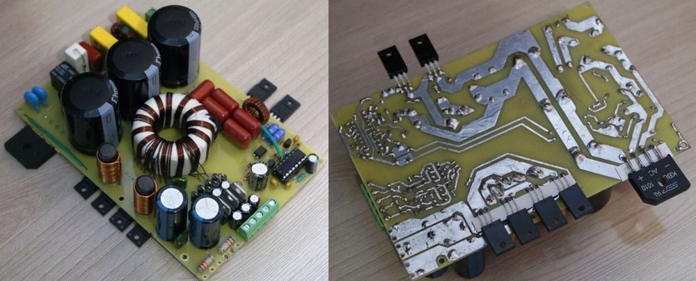
All SMPS circuits have an overcurrent position. The protection system is made according to the voltage drop on the shunt resistor added to the source leg of the mosfet connected to the 310v chassis. Since toroidal core is used, there is no need to use huge ETD series transformers at high power, but it is difficult to wind…
1000W SMPS circuit has been working flawlessly for years. New PCB design of the same system has been made. Output voltage (idle): +84 -84v output voltage at nominal load: + 72 -72v (-14.2%) constant power: 1000W; power at short-term peak currents: more than 1500 watts
Finally, the PCB design of the 220W SMPS circuit is made whole with the 2X110W amplifier circuit. 2x110W THD 0.005% (4 ohm 80W at 1kHz) with 4 ohm speaker.
FILE DOWNLOAD LINK LIST (in TXT format): 28190a.zip pass: 320volt.com
source: darkamp.ru