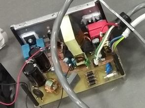
UC3845 LiFePO4 switch mode power supply charger. In order to simplify the connection, reduce the number of components and reduce the expected sources of problems, the following sections have been omitted around the UC3843 circuit. On pin number 2, overcurrent protection UC3843, a peak detector formed was launched components D10, C30 and R30 and pin 2 was connected to ground, The amplified measured current signal remained connected via a voltage divider R31 and R32 to pin 3, sensing the current of the control circuit UC3843.
The values of the divider components are calculated from relation and so left because of the entry control circuit operates in the range of 0 to 1 V. Behind the divider is as close as possible to the integrated circuit is connected by a blocking capacitor C7, Because circuits IC9 and IC2 must be supplied with 5 𝑉, it is for this purpose use the internal stabilizer of the UC3843 circuit from terminal 8. Increased control under voltage protection of the control circuit from 8.5 𝑉 to about 12 𝑉 is formed by components D11, C33 and R34 remains unchanged. The setting of the maximum shift and frequency of the PWM controller remained the same circuit.
![]()
Furthermore, the components were exchanged between the control PWM modulator and the first one gate of the protection period circuit. Because it is used to create protection periods TTL logic working with inputs in the range 0 to 5 𝑉, the original components will be omitted R36, T10, R35 and a voltage divider will be connected between the control and TTL cd4049D circuit, consisting of resistors R35 and R36. Voltage 0 to 13 𝑉 on output pin 6 (OUT) of the control circuit, the resistors will be reduced to 0 to 4.5 𝑉. The value of resistor R35 is selected to 2𝑘2 and resistor R36 is calculated according to the following equation
FILE DOWNLOAD LINK LIST (in TXT format): LINKS-26516b.zip


Circuit d’inverseur de soudage UC3843 UC3845 LiFePO4 alimenté
Chargeur d’alimentation à découpage UC3845 LiFePO4. Afin de simplifier la connexion, de réduire le nombre de composants et de réduire les sources de problèmes attendues, les sections suivantes ont été omises autour du circuit UC3843. Sur la broche numéro 2, protection contre les surintensités UC3843, un détecteur de crête formé a été lancé sur les composants D10, C30 et R30 et la broche 2 a été connectée à la masse.Le signal de courant mesuré amplifié est resté connecté via un diviseur de tension R31 et R32 à la broche 3, détectant le courant du circuit de commande UC3843.