An SMPS switched power supply project for power amplifiers with the IR2156 half-bridge mosfet driver IC from International Rectifier (currently acquired by Infineon Technologies). Brief information about IR 2156. The IR2156 is a half-bridge half-bridge converter controller with a built-in high voltage driver and a programmable oscillator. It was designed by the manufacturer as a controller to control the ballast of fluorescent lamps. However, it is used in other power electronics applications.
IR2156 Amplifier SMPS Power Supply circuit has Sprint layout PCB drawing and XLSX file prepared for output load resistor, overload resistor and power transformer calculation.
IR2156 General Features
The starting current of the IR2156 is around 200μA, which means no additional power supply is required for its operation (it is started with high value resistors and then the power supply unit automatically feeds itself.)
It has a built-in high voltage driver. Unlike the TL494 and SG3525, it has a built-in high voltage driver, so there is no need to use any additional driver ICs or driver transformers.
The programmable frequency allows, with the help of external elements, to set the required operating frequency, operating frequency and operating time in soft start mode, as well as the amount of dead time.
Soft start. In lamp ballasts, this function is necessary to preheat the lamp electrodes with low voltage before ignition (to reduce the ignition voltage and extend the lamp life). Softstart is a useful feature within the SMPS application.
Overload and short circuit protection. In the event of an overload or short circuit at the output of the power supply, the IR2156 driver will go into a disabled state and will not operate until the supply voltage is reset.
Protection against low mains voltage. This function protects the device from low voltage mains voltage. The protection activates when the input mains voltage, and therefore the voltage connected to the high voltage DC bus supply, falls below a predetermined threshold;
The IR2156 has an additional safety pin, SD, which stops the chip’s oscillator and switches it to UVLO mode when the voltage on the SD pin exceeds a threshold. For example, additional protective functions can be created, such as protection against overheating or turning off the power supply.
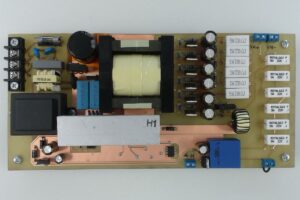
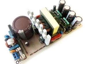
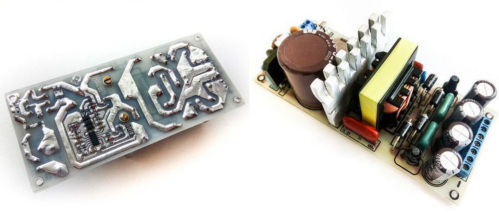
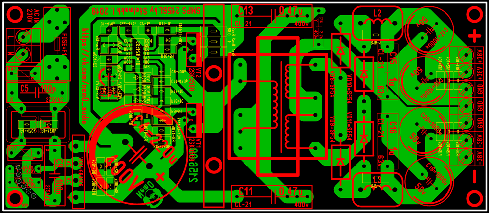
250W SMPS Circuit Diagram
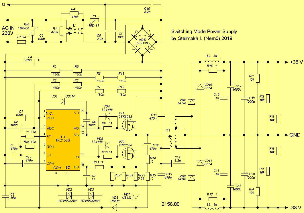
Power transformer T1 EE40 All windings are wound with litz wire. Primary winding 33 turns, 0.1 x 45 litz wire. Secondary output windings 8 turns each, 0.1 x 80 litz wire. Between the primary and secondary windings, 3 layers of insulation is made with lavsan tape.
File download LINK list (in TXT format) 28577a.zip password: 320volt.com
Source: cxem.net/pitanie/5-380.php