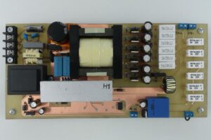
The 0.2V-80V switched power supply built on TL494 Integration can be used in various devices, motors, battery, battery charging processes, etc. designed for. There is additional SMPS circuit with TNY267 integrated circuit for feeding elements such as TL494, Fan, Relay. Like many circuit elements used in the SMPS Project, this material was supplied from PC power supplies.
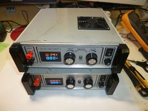
Adjustable SMPS Circuit parameters: Input voltage: 210V – 265V, Power consumption and current: max. 860W / 4.5A, Output voltage: 0.2V-80V, Ripple: up to about 0.3V, Adjustable Output current: 0-10 Amps., Short circuit current limitation: 14 Amps.
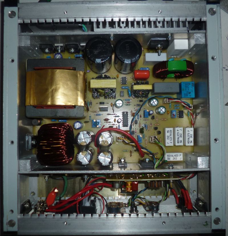
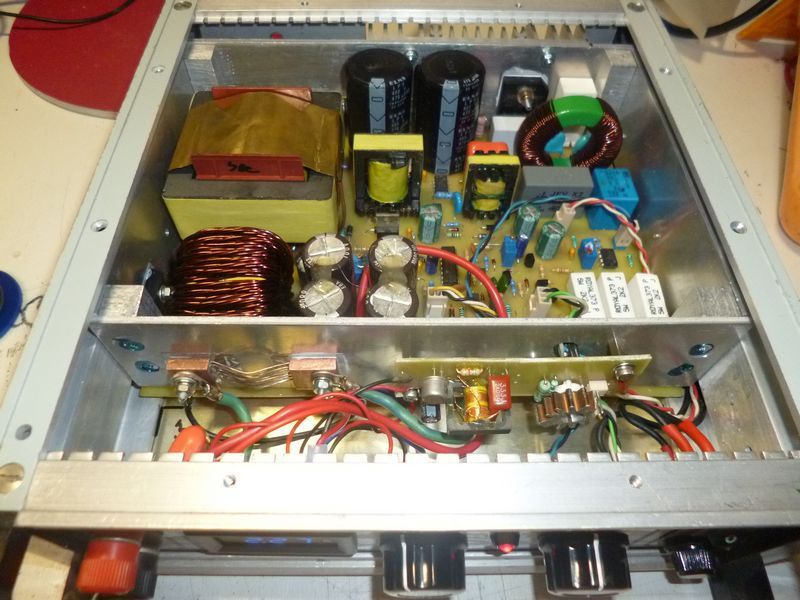
Output power transformer E65 can be tested with the ETD series instead. SMPS transformer calculations are made with the programs in the previous article “SMPS Converter Coil Transformer Calculation Programs“. Taken in the picture while wrapping the SMPS Transformer. TL494 Operating frequency 50Khz.
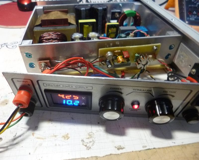
The shunt resistor handmade 15x15x5mm used for the ammeter gives two parallel 40mm 0.56mm wire brazed wire between two copper rectangles. Shunt used for current detection of SMPS Circuit is 0.1Ω 50W TO220 Transistor sheath
Conceptually, it is a single-acting pass-through converter, controlled by the known circuit TL494 in a single-acting circuit. The auxiliary source is a blocking converter controlled by the TNY267 circuit. The TL494 integrated circuit and part of the components can be obtained by disassembling an old computer source. The power supply has a continuous regulation of voltage and current. Furthermore, protection (Cycle by Cycle) against current overload of the end transistors and protection against overcurrent in the event of a short circuit at the output terminals.
It is built on a single-sided printed circuit board and all power components that need cooling are located on the edge of the board so that they can be easily attached to the heatsink. The diagram does not include a mains fuse, circuit breaker or reverse polarity protection diode, these must be added when mounting in the box. Furthermore, the construction does not solve the thermal protection either, because the cooling must be solved only according to the used cabinet.
parameters:
Input voltage: 210V to 265V ~
Power input and current taken from the network: max. 860W / 4.5A
Output voltage: 0.2V – 80V
Ripple: up to approx. 0.3V
Output current: 0 – 10A.
Short-circuit current limitation:> 14A
Dimensions (cabinet) W x D x H: 230 x 220 x 70mm
80V 10A SMPS Power Supply Circuit Diagram
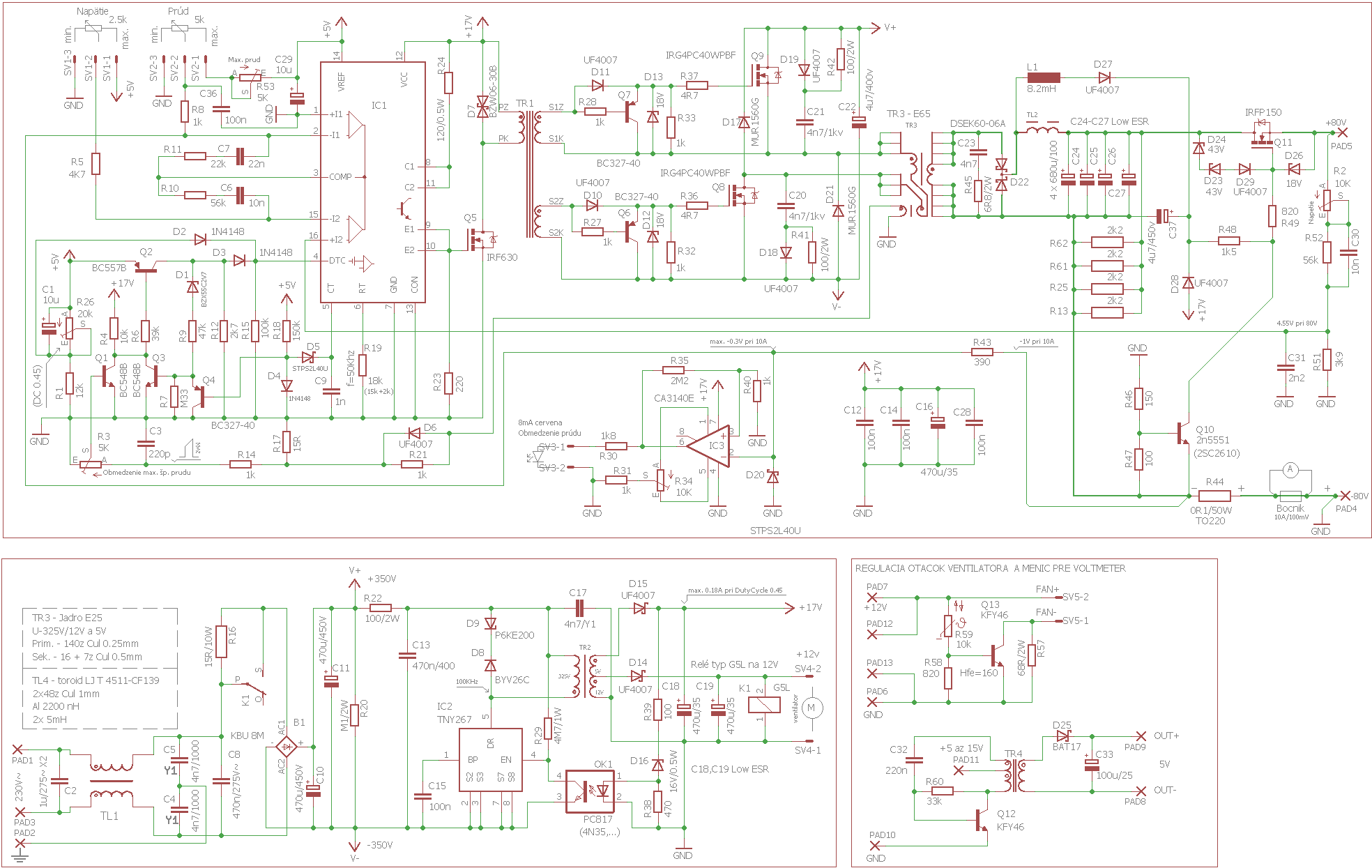
Eagle cad pcb, scheme etc. belonging to regulated SMPS circuit. all files: 10A-80V.rar
FILE DOWNLOAD LINK LIST (in TXT format): LINKS-27194a.zip
source: svetelektro.com/clanky/spinany-regulovatelny-zdroj-80v-10a-788.html