PC sound cards with multiple line outputs are commonplace than left and right channel for classical stereo reproduction. The described TDA2040 amplifier is designed especially for sound cards with four 2 + 1 + 1 output channels even those who have only a standard stereo signal, the amplifier described is complemented by simple custom ones circuits for creating additional channels.
Of course, the use of an TDA2040 amplifier is not limited to PC sound card, source signal can be any device consumer electronics with stereo nf analog output (tape recorder, player CDs and minidiscs, etc.). Only one The condition is to keep the output effective level The nf signal was about 0.7 to 1 volt, which is common for these types of devices. At higher level could easily be overexcited amplifier circuits, at a significantly lower level on the contrary, an amplifier would not be possible power up and play seemingly too quiet.
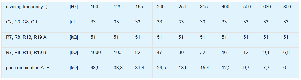
Three-channel reproduction with common the low frequency channel is based to the knowledge that human hearing can only to locate resources spatially higher frequencies. Therefore, it is enough to left and right channel send only these frequencies, the low frequencies are then transmitted in the same way together for both left and right channel. Common volume level acoustic signals (music, speech) it is not uniform throughout the spectrum decreases to higher frequencies. Therefore, most of the sound power is radiated just a common deep subwoofer and performance separated left and right “left” / “right” satellites can be significantly lower.
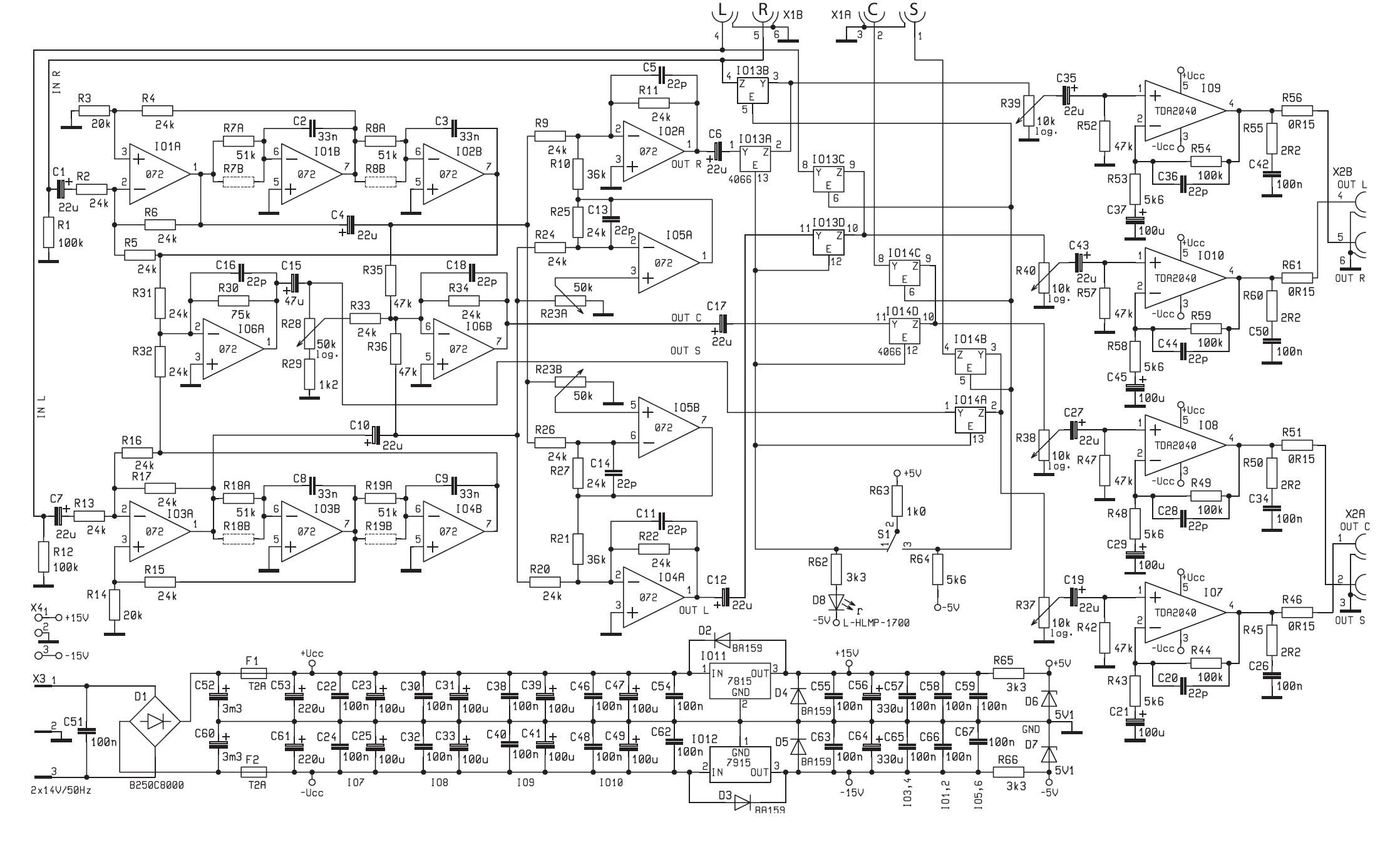
TDA2040 4 Channel Amplifier Circuit Schematic
This system, also referred to as 2 + 1, is often accompanied by a third satellite Centered between left and right satellites. His the task is to increase the resolution of directional localization signal for the listener. Resultant the four-channel transmission is then designated as type 2 + 1 + 1 . Six-channel is increasingly appearing system that arises from the previous one after adding two more satellites for the left and right channels. These but satellites are with respect to the listener placed from behind – that is for the listener created the perfect perception that simulates the size of the listening space Apparent movement of the source of the signal from the front backwards etc. The downside of the six-channel transmission is that it requires special recording source signals, that is also multi-channel or specially coded.
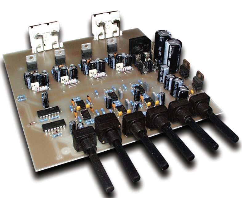
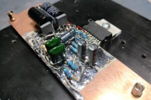
Amplifier realization The basic requirement was to create very TDA2040 cheap but relatively good quality
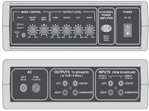
amplifier for home use with sufficient performance with the simplest design. A variant was chosen for implementation four channel amplifier with one common channel “Subwoofer” and three “left”, “right” satellites and “centers”. The amplifier can work in two modes:
a) “Effect” when processing signals only from two independent inputs (left and right) and using internal circuits to create them required four output channels
(b) “Direct” when it amplifies signals from four independent inputs without any of them further adjustments.
FILE DOWNLOAD LINK LIST (in TXT format): LINKS-26137.zip


ATTiny25 Three-phase 50 Hz Generator Circuit
ATTiny25 Three-phase 50 Hz Generator Circuit
Multifunctional sinusoidal three-phase signal generators are available on the market for testing inverters. However, in a situation where a simple control is necessary, to which a single frequency signal suffices, such a device becomes an unnecessary expense.nMoving the phase of an already generated analog signal would be difficult to perform, therefore it was decided to produce three sinusoids simultaneously. The low frequency of the output signal – only 50 Hz – allowed the PWM generator to be used with a reconstruction filter.
In this device the PWM transducer was implemented programmatically because three outputs were necessary. The frequency of the PWM signal is 12800 Hz and this is the maximum that was achieved by clocking ATtiny25 with a 16 MHz quartz resonator. The choice fell on this ATTiny25 microcontroller, because it can work with a quartz resonator in contrast to, for example, ATtiny13. In turn, the frequency of the clock signal translates into an output signal, thanks to which the built-in RC generator is not suitable for this application.
As an output buffer, an LM324 quad operational amplifier was used. Due to the asymmetrical power supply, the output signal must contain a constant component. The choice fell on this layout because of its availability and low price. You can try to exchange it for another type, which has a wider range of tolerated voltages. Mounting it in the stand allows quick replacement in case of damage caused by, for example, short circuit. The reconstruction filter is a very important element of the generator, DDS, because it allows to clear the spectrum of the output signal from the component derived from the clock and its harmonics. This arrangement allows the use of an uncomplicated filter due to the significant difference between the useful and the clock signal, respectively: 50 Hz and 12800 Hz.
A 2-stage, low-pass RC filter was used. The values of the elements were selected so that the influence of the buffer input resistance and the ATtiny25 output resistance would be negligible.
Amplificateur 4 canaux pour carte son TDA2040
Les cartes son PC avec plusieurs sorties ligne sont plus courantes que les canaux gauche et droit pour une reproduction stéréo classique. L’amplificateur TDA2040 décrit est spécialement conçu pour les cartes son avec quatre canaux de sortie 2 + 1 + 1, même ceux qui n’ont qu’un signal stéréo standard, l’amplificateur décrit est complété par de simples circuits personnalisés pour créer des canaux supplémentaires.
Bien sûr, l’utilisation d’un amplificateur TDA2040 n’est pas limitée à la carte son du PC, le signal source peut être n’importe quel appareil électronique grand public avec sortie analogique stéréo nf (magnétophone, lecteur CD et mini-disques, etc.). Un seul La condition est de maintenir le niveau effectif de sortie Le signal nf était d’environ 0,7 à 1 volt, ce qui est courant pour ces types d’appareils. À un niveau supérieur pourrait facilement être surexcité les circuits d’amplification, à un niveau nettement inférieur au contraire, un amplificateur ne serait pas possible de s’allumer et de jouer apparemment trop silencieux.
La reproduction à trois canaux avec le canal commun à basse fréquence est basée sur la connaissance que l’audition humaine ne peut que localiser les ressources à des fréquences spatialement plus élevées. Par conséquent, il suffit que les canaux gauche et droit envoient uniquement ces fréquences, les basses fréquences sont ensuite transmises de la même manière ensemble pour les canaux gauche et droit. Les signaux acoustiques de niveau de volume communs (musique, parole) ne sont pas uniformes dans tout le spectre, diminuent à des fréquences plus élevées. Par conséquent, la majeure partie de la puissance sonore est émise uniquement par un caisson de graves profond commun et les satellites gauche et droit «gauche» / «droit» séparés par les performances peuvent être considérablement plus faibles.
Schéma du circuit de l’amplificateur à 4 canaux TDA2040