Multifunctional sinusoidal three-phase signal generators are available on the market for testing inverters. However, in a situation where a simple control is necessary, to which a single frequency signal suffices, such a device becomes an unnecessary expense.nMoving the phase of an already generated analog signal would be difficult to perform, therefore it was decided to produce three sinusoids simultaneously. The low frequency of the output signal – only 50 Hz – allowed the PWM generator to be used with a reconstruction filter.
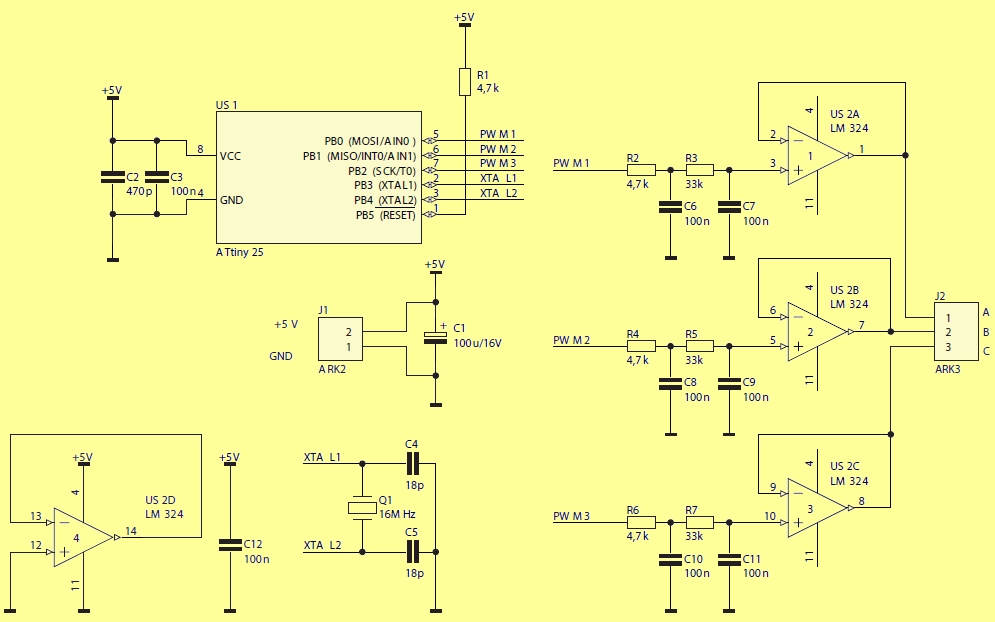
In this device the PWM transducer was implemented programmatically because three outputs were necessary. The frequency of the PWM signal is 12800 Hz and this is the maximum that was achieved by clocking ATtiny25 with a 16 MHz quartz resonator. The choice fell on this ATTiny25 microcontroller, because it can work with a quartz resonator in contrast to, for example, ATtiny13. In turn, the frequency of the clock signal translates into an output signal, thanks to which the built-in RC generator is not suitable for this application.
As an output buffer, an LM324 quad operational amplifier was used. Due to the asymmetrical power supply, the output signal must contain a constant component. The choice fell on this layout because of its availability and low price. You can try to exchange it for another type, which has a wider range of tolerated voltages. Mounting it in the stand allows quick replacement in case of damage caused by, for example, short circuit. The reconstruction filter is a very important element of the generator, DDS, because it allows to clear the spectrum of the output signal from the component derived from the clock and its harmonics. This arrangement allows the use of an uncomplicated filter due to the significant difference between the useful and the clock signal, respectively: 50 Hz and 12800 Hz.
A 2-stage, low-pass RC filter was used. The values of the elements were selected so that the influence of the buffer input resistance and the ATtiny25 output resistance would be negligible.
It can be read from this that the suppression of the 50 Hz component is about 4 dB, and the 12,8 kHz component is about 80 dB. This means that the interference from the PWM signal will be weaker by approx. 76 dB, which should not be visible in the background of the output signal.
The oscillogram of two output waveforms is shown in Figure 3. They are, as intended, shifted in phase. At the bottom of the sine wave you can see the barely noticeable flattening caused by LM324 restriction.
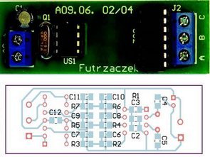
50 Hz Generator Circuit Schematic
If such a distortion turned out to be unacceptable, you can, as mentioned earlier, try to replace this system with another one, eg MCP604.
The signal parameters are as follows: frequency 50 Hz, constant component approx. 2.25 V, peak-to-peak value approx. 2.3 V.
Visual assessment of the time course is not everything. The amplitude spectrum of a single signal is presented in Figure 4. Its SFDR can be estimated at approx. 30 dB.
The microcontroller should be programmed and the source of the clock signal should be changed to an external 16 MHz quartz resonator (CKSEL 3 … 0 = 1111) and the CKDIV8 bit should be switched off. The device does not require calibration and is immediately ready to work. Powered by 5 V, it consumes approx. 15 mA.
Output B is shifted in relation to A by + 120 °, and C in relation to A by + 240 °. The fixed component from the output can be cut off, eg with capacitors, and the signal itself can be amplified or suppressed, depending on the needs.
![]()
FILE DOWNLOAD LINK LIST (in TXT format): LINKS-26150.zip


4 Channel Amplifier For Sound Card TDA2040
4 Channel Amplifier For Sound Card TDA2040
PC sound cards with multiple line outputs are commonplace than left and right channel for classical stereo reproduction. The described TDA2040 amplifier is designed especially for sound cards with four 2 + 1 + 1 output channels even those who have only a standard stereo signal, the amplifier described is complemented by simple custom ones circuits for creating additional channels.
Of course, the use of an TDA2040 amplifier is not limited to PC sound card, source signal can be any device consumer electronics with stereo nf analog output (tape recorder, player CDs and minidiscs, etc.). Only one The condition is to keep the output effective level The nf signal was about 0.7 to 1 volt, which is common for these types of devices. At higher level could easily be overexcited amplifier circuits, at a significantly lower level on the contrary, an amplifier would not be possible power up and play seemingly too quiet.
Three-channel reproduction with common the low frequency channel is based to the knowledge that human hearing can only to locate resources spatially higher frequencies. Therefore, it is enough to left and right channel send only these frequencies, the low frequencies are then transmitted in the same way together for both left and right channel. Common volume level acoustic signals (music, speech) it is not uniform throughout the spectrum decreases to higher frequencies. Therefore, most of the sound power is radiated just a common deep subwoofer and performance separated left and right “left” / “right” satellites can be significantly lower.
TDA2040 4 Channel Amplifier Circuit Schematic
Circuit générateur triphasé 50 Hz ATTiny25
Des générateurs de signaux triphasés sinusoïdaux multifonctionnels sont disponibles sur le marché pour tester les onduleurs. Cependant, dans une situation où une simple commande est nécessaire, à laquelle un signal à fréquence unique suffit, un tel dispositif devient une dépense inutile.n Déplacer la phase d’un signal analogique déjà généré serait difficile à réaliser, il a donc été décidé de produire trois sinusoïdes simultanément. La basse fréquence du signal de sortie – seulement 50 Hz – a permis au générateur PWM d’être utilisé avec un filtre de reconstruction.
Dans cet appareil, le transducteur PWM a été implémenté par programme car trois sorties étaient nécessaires. La fréquence du signal PWM est de 12800 Hz et c’est le maximum qui a été atteint en cadencant ATtiny25 avec un résonateur à quartz de 16 MHz. Le choix s’est porté sur ce microcontrôleur ATTiny25, car il peut fonctionner avec un résonateur à quartz contrairement, par exemple, à ATtiny13. À son tour, la fréquence du signal d’horloge se traduit par un signal de sortie, grâce auquel le générateur RC intégré ne convient pas à cette application.