A difficult-to-implement 3-phase inverter project. It can provide inspiration for different projects, and its documentation is very good. Full project files prepared with Altium Designer, heatsink 3D drawings, STM32 source codes, libraries, etc. The entire project has been shared. Advanced ICs such as IR2233J, STM32G474RET6, ADUM1201, TC4427VOA, LTS15-NP, L5970D, UCC2813, etc. are used for the DC DC converter and 3x325V generation. It also includes many communication protocols such as ethernet, can, and usb.
Design of the voltage converter and a three-phase inverter. The converter will be able to generate a three-phase output voltage with an adjustable waveform, primarily in harmonic sine form.
The system will allow the sine amplitude (output voltage) to be adjusted within a certain range, as well as fine corrections to be made in the output frequency and phase shifts. In this way, for example, a two-phase 120 V distribution network or different test signals can be generated.

The main purpose of this work is to design and implement a device that converts the electrical energy stored in the battery pack used in a residential solar power plant into three-phase alternating current grid voltage.
The resulting system can be used both to power everyday electrical devices and to test these devices. The device has been designed with the flexibility to generate not only pure sinusoidal outputs, but also complex waveforms consisting of multiple harmonic components.
Parameters such as output voltage, current, frequency, and delay between phases can be adjusted by the user. Thanks to these features, the system offers a highly flexible structure for powering and testing different electrical loads.
Output waveforms can be selected by the user through pre-generated look-up tables, while frequency adjustment can be performed over a wide range that allows testing of switched-mode power converters and rotating generator control systems. The ability to adjust phase positions separately also enables precise control of phase synchronization.
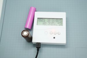
System settings are made through a user console operating via a touch panel and a local web interface hosted on the control board. The instantaneous operating status of the inverter is presented to the user both on the LCD screen and in the web interface.
3-Phase Inverter System Architecture
Contents

The entire system consists of two main sections: the power converter (inverter) section and the control section that provides communication with the user. The control unit includes the interfaces required for connection to a computer or local network, the LCD screen, and peripherals that support the connection of external memories such as an SD card for data transfer.
The power converter board also includes a serial terminal connection that provides limited control capability. This terminal is designed to be used for testing and service operations performed without the control board. The control unit allows multiple inverters to be connected at the same time and operated synchronously through a dedicated synchronization line.
In addition, other devices using a compatible custom communication protocol, such as MPPT charge controllers or battery status monitoring systems, can also be connected to the control unit. However, these additional devices have been left outside the scope of this work.
Battery Voltage Processing and Inverter Structure

Solar panels generate direct current (DC), and this energy is usually stored in batteries. Since high-voltage battery systems would be costly and inefficient, a DC/DC converter such as an MPPT is generally placed between the solar panels and the batteries.
This converter reduces the panel voltage and brings it to a level suitable for the battery pack.
However, the low-voltage and DC-character battery output is not suitable for most electrical devices. Most electrical devices used today require sinusoidal AC voltage whose amplitude and frequency vary depending on the country.
In Turkey and Europe, these values are 230V RMS per phase and 50Hz, with a 120° phase difference between the three phases.
Simple inverters generally produce a square wave or stepped wave output. Although these waveforms are sufficient for many devices, they are not suitable for systems that are sensitive to sine waves, such as motors and inductive loads. In addition, these types of inverters generate electromagnetic interference due to their high harmonic content and may cause problems in some devices.
DC/DC Converter and DC Link

For an inverter with an LC filter to operate properly, a sufficiently high DC-link voltage corresponding to the amplitude of the output sine wave is required.
For this reason, a DC/DC converter in a full-bridge structure consisting of four switching elements must be used in order to obtain high voltage from the battery voltage.
The DC link must be designed with enough capacity to handle not only the nominal power but also the additional load caused by the sinusoidal output having lower effective power compared to its DC equivalent.
Since the effective power of the sine wave corresponds to approximately 63% of the DC voltage with the same amplitude, the converter must have enough power to compensate for this difference.
Control Structure and Microcontroller Usage

Although the DC/DC converter can be controlled with analog controllers, a commercial analog solution for generating a three-phase sinusoidal output with adjustable amplitude, phase, and frequency is not practical.
For this reason, a microcontroller-based control approach has been adopted in the system.
Modern microcontrollers have sufficient processing power to control both the DC/DC converter and the three-phase inverter, while also performing user interface and communication tasks.
In particular, the STM32 family is suitable for such applications with its fast ADCs, timers, DMA units, and hardware floating-point processors (FPU). STM32F429ZIT6

![]()