
The designed laser light barrier can provide reliable detection at a range of 100 meters and more. In this design, which uses a continuously operating wave (CW) laser diode in the visible light range with low-frequency (AF) amplitude modulation, the theoretical detection distance is over 1000 meters.
In practical applications, distances of up to 100 meters can be reliably achieved. At this point, the most important factors determining the success of the system are the solid mounting, precise alignment, and mechanical stability of the transmitter and receiver.
Thanks to these features, the security of large buildings, wide open areas, and detached properties can be provided with a relatively simple installation.
In addition, the laser light barrier also offers many areas of use in industrial automation and technical applications.
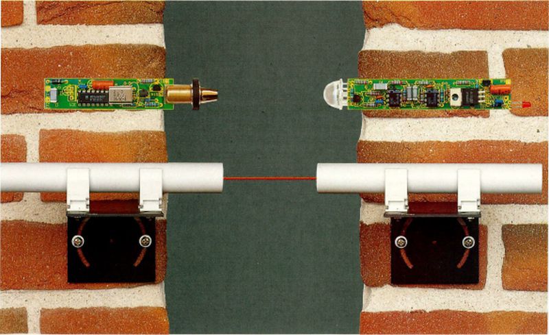
The transmitter laser module consumes approximately 50mA current, and the entire electronic circuit, including modulation, is placed inside an epoxy-filled plastic tube.
The receiver side is similarly located inside a plastic tube together with the demodulator circuit. This structure makes installation extremely easy (for example, with mounting clamps).
The open-collector driver at the receiver output provides information on whether the laser beam is being received or whether it has been interrupted.
Laser Barrier Circuit Structure
Contents
In applications requiring long range, lasers offer significant advantages compared to conventional LED-based light barriers.
Since laser tubes are both costly and unnecessarily sensitive for such applications, laser diodes operating in the visible range have been preferred in this design.
Another important element is the collimator optic placed in front of the laser diode. Thanks to this optical structure, the laser beam is made extremely narrow and directional.
Noise Immunity: In order to achieve high noise immunity, the system operates with AF-AM (low-frequency amplitude modulation). The transmitter and receiver circuits are designed independently from each other.
Laser Transmitter Circuit


The transmitter circuit operates with a 5V supply voltage regulated by the 7805 IC. The input voltage between 8–20 V is applied to the regulator through a reverse-polarity protection diode.
Capacitors are used to suppress voltage fluctuations and the tendency to oscillate.
The modulation frequency is generated using the CD4060 IC. The 2MHz clock signal generated with the help of an external crystal oscillator is divided inside the IC to obtain a frequency of 122 Hz. This signal is used to drive the laser diode.
A fixed supply of approximately 3V for the laser diode is provided with the help of a transistor and a Zener diode. With a second transistor, this voltage is modulated with the 122 Hz signal and applied to the laser diode.
Laser Barrier Receiver Circuit


In the LM358 laser receiver circuit, a stabilized power supply is also obtained from the 8–20 V input voltage. Safe operation is ensured with reverse-polarity protection and filtering capacitors.
A BPW34 photodiode is used as the sensor. The operating point of the photodiode is automatically adjusted with the help of an operational amplifier and a transistor.
In this way, changes in ambient light are balanced, and maximum sensitivity is maintained independently of environmental illumination.
The signal from the photodiode is passed through a band-pass filter with a 122 Hz center frequency and an approximately 5 Hz bandwidth. This narrow band greatly suppresses noise that may come from the environment.
The filtered signal is amplified, rectified, and evaluated by a comparator.
When the signal exceeds the specified threshold value, the output becomes active, the status is indicated by an LED, and external loads can be driven through the open-collector output.
If inductive loads such as relays are used, a flyback diode must be connected across the load.
Laser Barrier Assembly and Mechanical Structure
The transmitter and receiver circuits are placed inside plastic tubes with lengths of 13 cm and 17 cm, respectively.
The inner surface of the receiver tube should be selected in black in order to prevent reflections.
The circuit boards are designed with double-sided component placement due to limited space.
After all circuit elements are placed, the first function test is performed.
The system is checked by performing alignment at a distance of approximately 1 meter.
After the function test, the circuits are filled with epoxy and completely insulated.
Installation and Adjustment Recommendations
The receiver should be protected from direct sunlight as much as possible.
At long distances, if the alignment process is performed in the evening hours, the laser beam can be seen more easily.
The transmitter unit must be mounted on a solid and vibration-free surface (concrete wall, column, etc.).
Precise aiming is possible thanks to adjustable metal mounting brackets.
Laser Barrier PCB Layouts

The PCB layout is single-layer in both modules. The component assembly of the laser transmitter circuit is not too complicated.
The PCB layout of the laser receiver circuit has been kept as small as possible. Therefore, some components are soldered from the underside of the PCB.
Perform the assembly carefully by referring to the completed circuit and the PCB top view.
The PCB copies copied with Sprint Layout 6 were checked but not tested. PCB Gerber and PDF files have been added to the file.
source: de.elv.com/p/laser-lichtschranke-mit-hoher-reichweite-P202883/


