Years ago, I had built a TDA7265 amplifier circuit, but I did not know it was this good at that time. Back then, high power was more interesting, and I probably did not examine the datasheet details much 🙂
When I saw the article “TDA7292 / TDA7265 / TDA7269 DIY Guide – 40W / 30W / 14W Stereo Single-Chip Power Amplifiers”, I decided to build a TDA7265 amplifier circuit again.
@Electro-dan has given many details in his article: https://electro-dan.co.uk/electronics/TDA7292_TDA7265.aspx
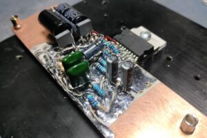
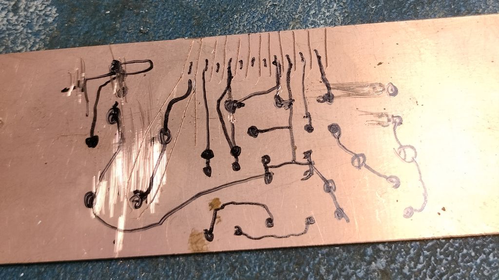
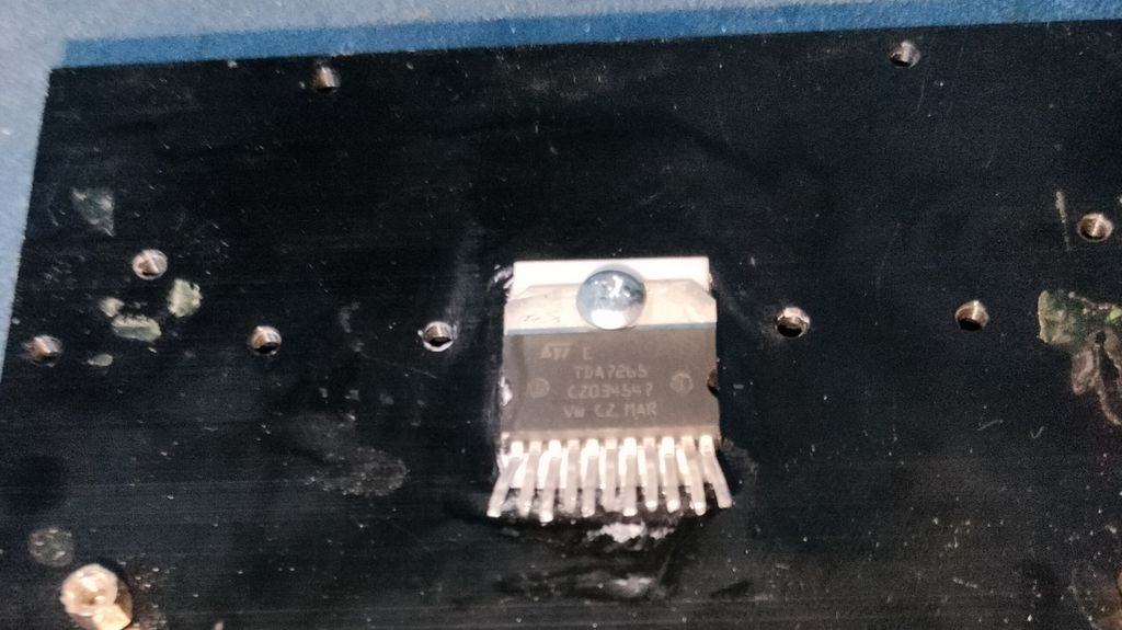
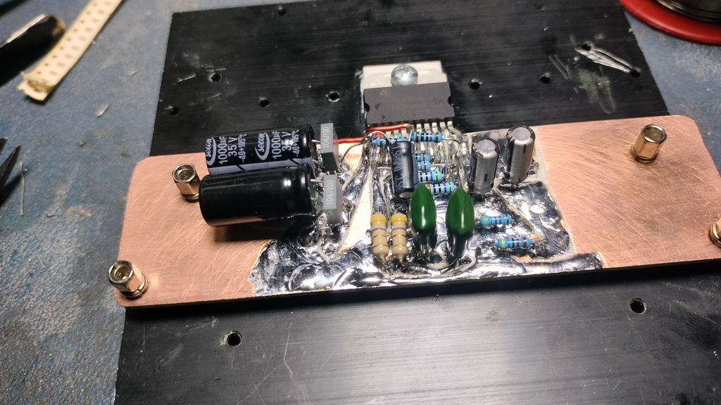
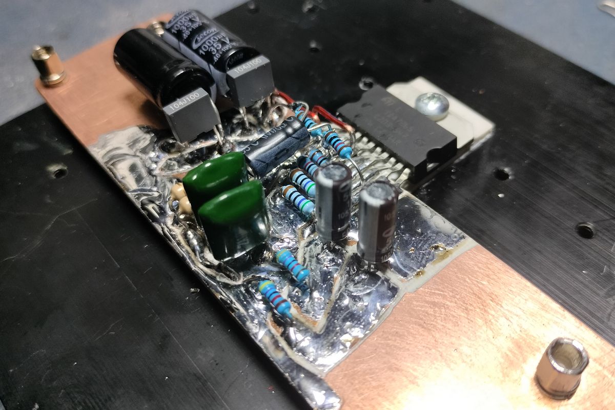
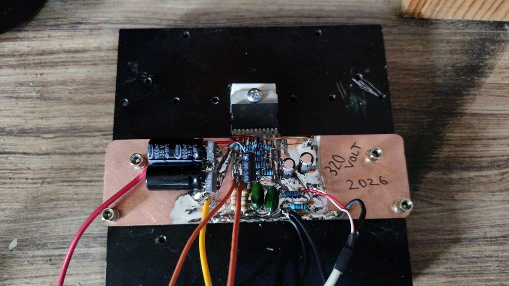
The author uses the old PCB etching method, although it is much more advanced compared to my early years… I prepared the PCB by directly scraping it with a hobby knife, partly out of laziness and partly for a change 🙂 I straightened the TDA7265 pins with pliers for assembly. There are very few components in the circuit setup, and the sound quality is good..
Performance Differences of the ICs
Contents
The table below compares the performance differences of the TDA7292, TDA7269A, TDA7265, and TDA7265B amplifier ICs. Remember that the voltage range is from the minimum to the maximum operating limits; for reliability, use a voltage source 2V below the maximum limit.
The 3 ICs are manufactured by ST-Microelectronics, and some are also manufactured by UTC. The features of each IC differ significantly; TDA7292 is the most powerful, while TDA7269 is the lowest-power one. For other models and TDA7265 heatsink calculation, you can use the Amplifier IC Heatsink Calculation tool.
All amplifier ICs are Hi-Fi/AV ICs designed to drive 8 ohm speakers rather than 4 ohm speakers.
| Package | Supply Voltage Range | 10% power, 1kHz THD – 8 ohm | 10% power, 1kHz THD – 4 ohm | 1% power, 1kHz THD – 8 ohm | 1% power, 1kHz THD – 4 ohm | Peak current limit |
|---|---|---|---|---|---|---|
| TDA7292 | +/-8V to +/-33V | 40W + 40W, +/-26V | 31W + 31W, +/-18V | 30W + 30W, +/-26V | 24W + 24W, +/-18V | 5A |
| TDA7265B | +/-8V to +/-33V | 30W + 30W, +/-23V | – | 25W + 25W, +/-23V | – | 5A |
| TDA7265 | +/-5V to +/-25V | 25W + 25W, +/-20V | 25W + 25W, +/-16V | 20W + 20W, +/-20V | 20W + 20W, +/-16V | 4.5A |
| TDA7269A | +/-5V to +/-20V | 14W + 14W, +/-16V | 10W + 10W, +/-12.5V | 11W + 11W, +/-16V | 7.5W + 7.5W, +/-12.5V | 3A |
TDA7265B is an improved version of TDA7265, with a capacity almost equal to TDA7292. The datasheet states that it can reach 40W with a +/-26V supply, but this is a somewhat forced value. There is no specified power value for 4 ohm speakers, but it is expected to operate with performance close to TDA7292 at 4 ohm.
TDA7265 Hi-Fi Amplifier Test Video
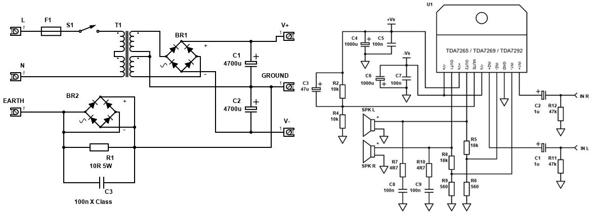
TDA7265 Amplifier and Power Supply Circuit Schematic
TDA7265 Amplifier Circuit Component List
| U1 | TDA7292, TDA7265, TDA7265B or TDA7269A | 1 |
| R2,R4 | 10k ohm Resistor, ¼W Metal Film, 1% | 2 |
| R5,R8 | 18k ohm Resistor, ¼W Metal Film, 1% | 2 |
| R6,R9 | 560 ohm Resistor, ¼W Metal Film, 1% | 2 |
| R7,R10 | 4.7 ohm resistor, 1W carbon, 5% | 2 |
| R11,R12 | 47k ohm Resistor, ¼W Metal Film, 1% | 2 |
| C1,C2 | 1µF Capacitor, Polyester Film/Box Type (Best) or 16V Electrolytic Capacitor | 2 |
| C3 | 47µF Capacitor, 35V+ Electrolytic (use 50V for TDA7292) | 1 |
| C4,C6 | 1000µF Capacitor, 35V+ Electrolytic (use 40V for TDA7292) | 2 |
| C5,C7 | 100nF Capacitor, 50V+ Ceramic X7R or MLCC | 2 |
| C8,C9 | 100nF Capacitor, 50V+ Polyester Film/Foil/Orange Drop (Best) or Ceramic X7R | 2 |
| At L,R | 2.54 mm header 4-pin | 1 |
| +Vs,-Vs,GND | 3.96 mm CH W2B Molex 5239/KK396 3-pin | 1 |
| Spk R, Spk L | 6.3 mm Quick Connect (Spade) PCB Separator | 1 |
| Heatsink, cable, connectors | ~ |
Inside the file, there is the Sprint Layout 6 version of the PCB drawing shared in @Electro-dan’s article and the stereo and mono PCB drawings prepared by @tutlay ( tutlay.ru/radioshemy/r2/52-usilitel-na-tda7265-2x25vt.html)
Note: Reinforce the audio outputs and power supply lines with solder filling. In the PCB drawings, these tracks had to be drawn thin because they pass between the pins, so reinforcing the tracks is essential.


