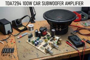
A TDA7294-based subwoofer amplifier design prepared for in-car use. The TDA7294 IC is used in the output stage, and the circuit can deliver approximately 100W level power. Since a high symmetrical supply is not directly available in the vehicle electrical system, the supply around +30V / -30V required by the amplifier is obtained with an additional DC-DC converter stage.
I had previously shared a similar project: TDA7294 Bass car amplifier TL494 SMPS supply. The PCB design of this project looks very good, so let it be included in the archive.
The TL494 is used in the DC-DC converter stage. TL494 is an easy-to-find and practical PWM control IC that has been preferred for many years in car amplifiers and various SMPS applications. You can find a significant portion of the parts used from old PC power supplies or some computer boards.
According to the source content, this amplifier is not a design tried for the first time; it is stated that similar applications have been made before and therefore no basic problem is seen in terms of reliability. It is an ideal circuit especially for those looking for a low-cost but functional solution in car subwoofer applications.
General Structure of the Circuit
Contents
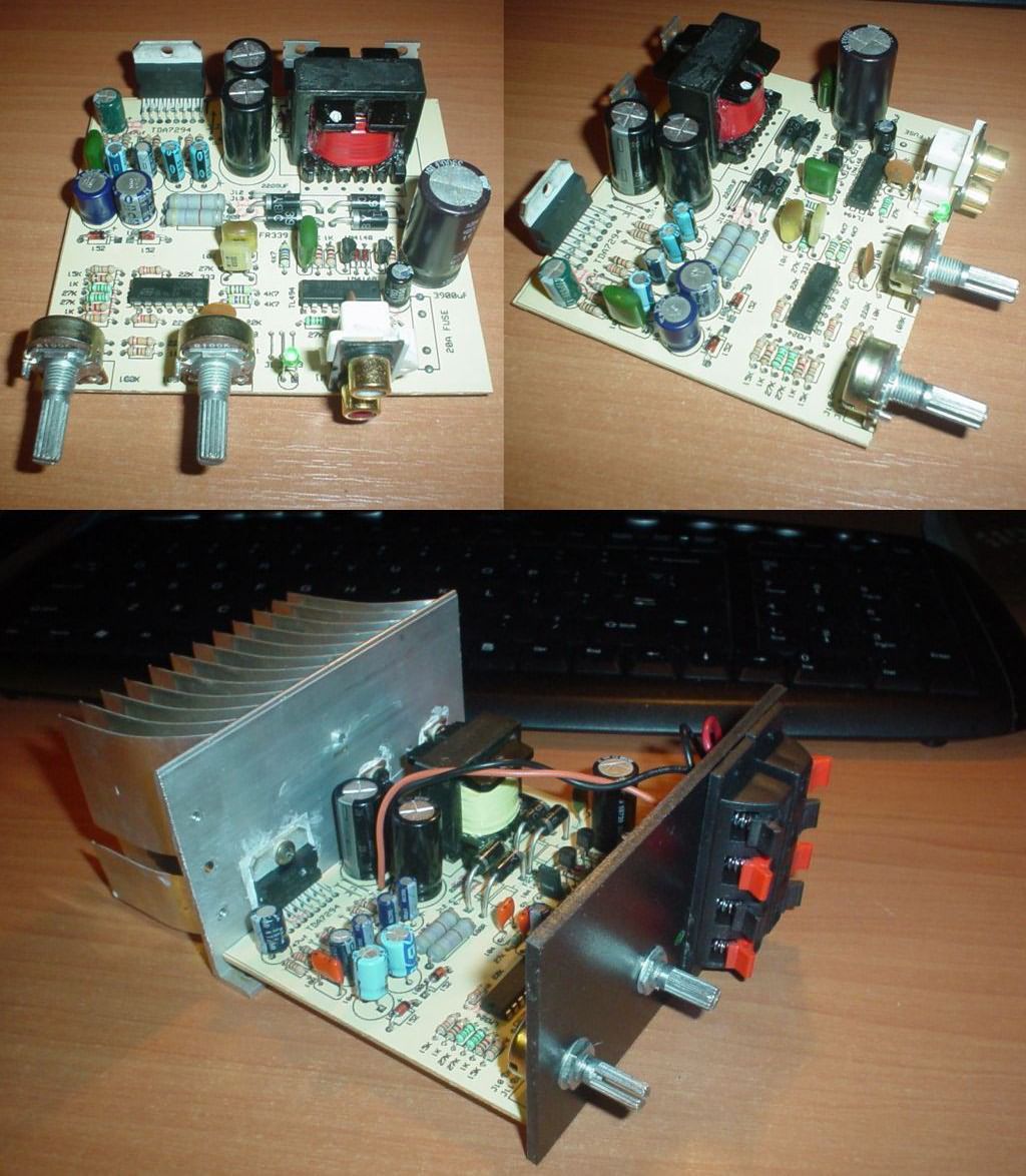
This system consists of two main sections:
- Amplifier stage: TDA7294
- Power supply converter stage: A TL494 DC-DC converter is used to generate symmetrical high voltage from the 12V car battery.
DC-DC Converter Stage
Since 12V DC is generally available in the vehicle environment, voltage boosting and symmetrical power supply generation are required for ICs such as the TDA7294 to deliver higher output power. For this reason, an SMPS stage that converts 12V to approximately +30V / -30V has been added. This method is one of the classic solutions seen in many car amplifiers. RFZ46 MOSFET was preferred as the power switching elements. This structure offers a very common and applicable topology for car amplifiers.
This type of converter built with the TL494 can operate quite efficiently with correct transformer winding and suitable MOSFET selection. The main purpose here is to boost the 12V voltage taken from the car battery and generate the symmetrical supply required by the amplifier stage. Thanks to the symmetrical supply, the TDA7294 can provide a more suitable output swing for driving a subwoofer.
It is stated that the transformer used in the circuit was removed from a computer power supply and recycled.
Transformer Winding Information
According to the given information, the winding structure of the transformer is as follows:
- Primary winding: 2 x 10 turns with two parallel wires of 0.7 mm diameter
- Secondary winding: 2 x 20 turns with 0.9 mm wire
It is stated that this winding structure is sufficient for the power consumption of the amplifier. However, an important technical warning is also given here. Especially in high-frequency SMPS applications, using a single thick wire may not always be the best solution. The reason for this is that, due to the skin effect that occurs at high frequency, the entire conductor cannot be used efficiently.
Therefore, instead of using a single thicker wire in the primary winding, it is considered more suitable to use multiple thinner wires connected in parallel. The content especially draws attention to the following points:
- Using a single 0.9 mm wire with 10 turns in the primary winding is not considered a good option.
- If a single conductor will be used, wire larger than 1.0 mm may be considered; however, this is also not ideal at high frequency.
- 2 x 10 turns with two 0.9 mm wires connected in parallel can work.
- 2 x 10 turns with three 0.7 mm wires connected in parallel can give even better results.
This information is important especially for those who want to reuse old PC power supply transformers. Because when the core size is fixed, a balance must be established between suitable power transfer and physically fitting the winding onto the core.
Note: If you do not want to deal with disassembling and rewinding the transformer, you can examine the method explained in the “DC DC Converter 200W 2X30V SG3524 SG3525 Using EI33 Transformer” article.
What Do the 1K Resistor and 104 Capacitor Placed Between Grounds Do?
One of the noticeable points in the circuit is the use of a 1K resistor and 104-coded capacitor placed between the converter ground and the amplifier ground. This section is important especially for reducing ground loop and interference problems that are frequently seen in car audio systems.
It is stated that this component group has several basic functions:
1) It helps reduce the ground loop
The amplifier and the car music player are usually connected to the same battery. While the audio signal is carried from the music player to the amplifier through the RCA line, if a direct and uncontrolled connection is formed between the converter ground and the amplifier ground, a ground loop may occur. This can cause hum, background noise, and interference problems.
2) It limits unwanted current paths in case of a faulty or weak negative connection
If the contact of the negative line in the vehicle is weak or missing, there is a risk that the converter may try to be powered through the signal ground. Especially when the positive terminal is connected to the amplifier first and the RCA cables are plugged in, the signal ground coming from the music player may unintentionally become a return path. This can cause both interference and stress on the equipment.
3) It contributes to audio system safety and stability
This small RC network is a detail that is sometimes neglected in car amplifiers but can be useful in practice. It can function both in terms of noise control and limiting unwanted ground currents.
PCB Size and Drawing Program
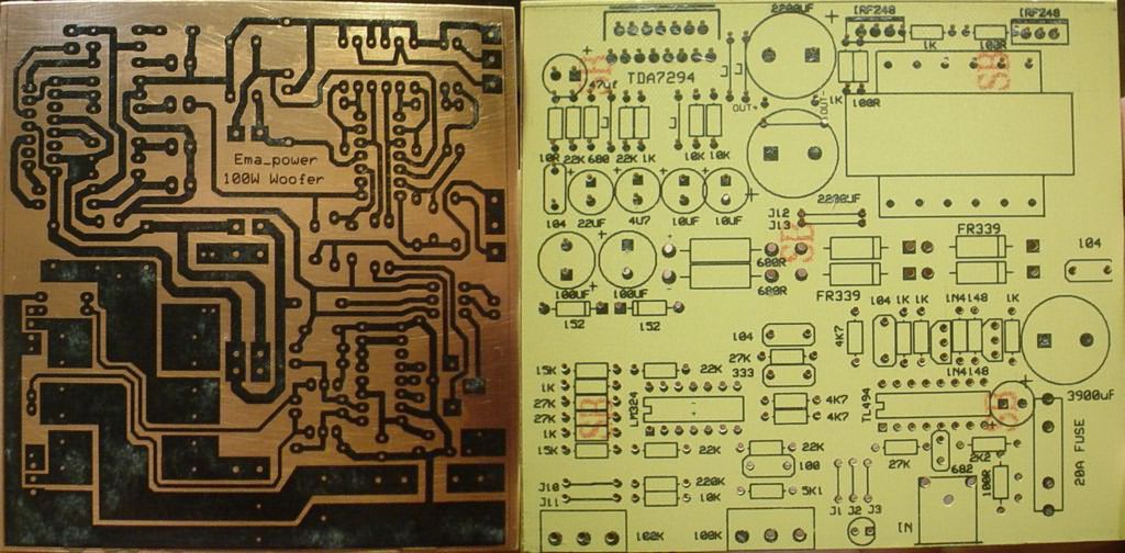
According to the given information, the size of the printed circuit board is specified as 105 x 98 mm. This size is not considered very large for in-car applications and is relatively easy to place.
It is stated that the PCB design was prepared with the ExpressPCB program. ExpressPCB is a simple printed circuit design software frequently used especially in older amateur and hobby projects. For users who have this software, it may be easier to examine the existing layout logic.
Source: elforum.info/topic/53211-amplificator-subwoofer-auto-100w/


