With the widespread use of portable devices, seeing the real capacity of single-cell Li-Ion and Li-Pol batteries in the 3.7V class has become more important than ever. A battery that is labeled 2500 mAh on paper can deliver much lower capacity in real use.
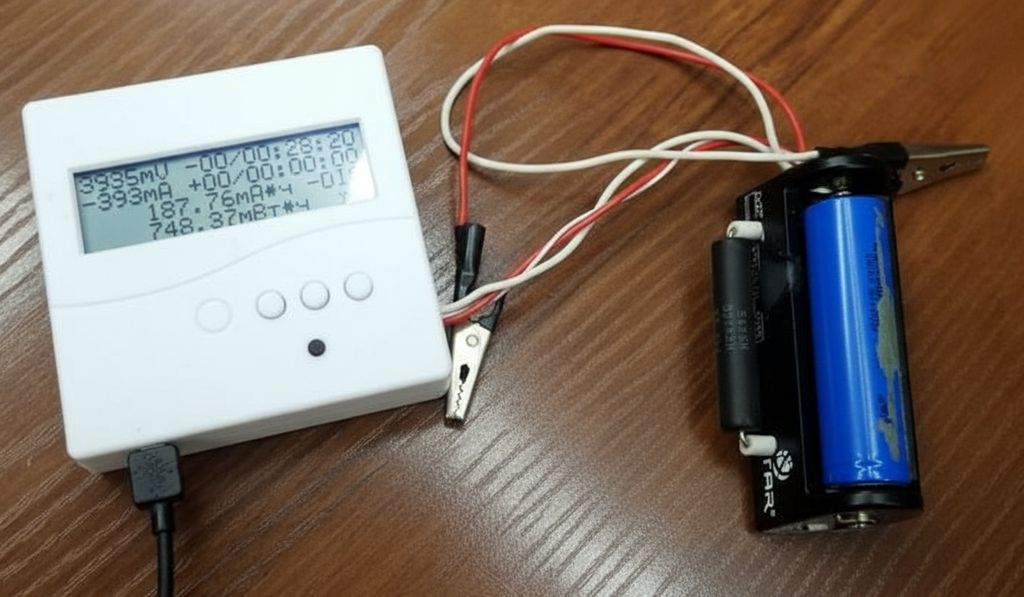
Especially with second-hand battery cells, dismantled battery packs, or batteries that have been stored for a long time, the most accurate way to understand this is to perform a controlled discharge test.
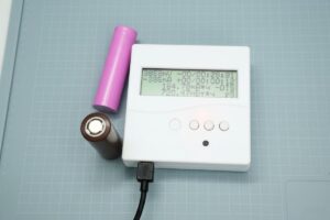
The device described in this project focuses exactly on this task. It discharges single-cell lithium batteries under a controlled load, monitors the voltage, counts the time, and calculates the energy delivered by the battery in both mAh and mWh. Moreover, after the test is completed, it switches to charging mode, making it practical on the usage side as well.
For those working with common cells such as 18650, this type of meter provides serious benefits, especially during 18650 battery selection and sorting.
Battery Capacity Meter
Contents
- 1 Battery Capacity Meter
- 2 Operating principle of the Battery Capacity Meter Circuit
- 3 What do the main blocks in the schematic do?
- 4 Load options and approximate current values
- 5 Why are mAh and mWh shown together?
- 6 What information is shown on the display?
- 7 Button and LED functions
- 8 The most important point in practice: accuracy and limits
- 9 Short notes about the components in the schematic
- 10 Things to pay attention to during assembly and use
- 11 General evaluation
It is often not possible to understand the health of a battery only by looking at its no-load voltage. Internal resistance measurement also gives an idea, but it does not directly show the real capacity.
What really matters is how long the battery can deliver energy under a specific load.
This circuit does exactly that: it connects the battery to a certain resistive load, monitors the voltage, and accumulates the energy calculation throughout the discharge process.
This approach is especially useful for selecting cells to be used in hobby projects. For those who want to look at the subject from a general perspective, basic information about Li-Ion, Li-Po, and LiFePO4 batteries also makes it easier to understand what this device measures.
Operating principle of the Battery Capacity Meter Circuit

At the center of the system is the STM32F051K6 microcontroller shown as DD1. This microcontroller measures the battery voltage through the ADC, selects the connected load, runs the time counters, drives the LCD screen, and controls the mode transitions.
On the power supply side, 3V is obtained from the 5V input with LM1117-3.0. This 3V line powers both the microcontroller and the I2C-controlled LCD module. A 128×32 graphic LCD is used as the display, and the connection is made over I2C. R1 and R2 act as pull-up resistors here.
Charging the battery is handled with a separate logic. The TC4056A-based charging module seen in the schematic is used to charge single-cell Li-Ion/Li-Pol batteries up to 4.2V.
The charging path is switched on and off with the IRLML6402 P-channel MOSFET shown as VT1. The discharge loads are switched with the IRLML2502 MOSFETs shown as VT2 and VT3.
What do the main blocks in the schematic do?
It becomes easier to understand the circuit when it is divided into four parts.
- Power and regulation section: 3V is generated from the 5V input. The microcontroller and the display are powered from this line.
- Measurement section: The battery voltage is carried to the ADC input through the R8 and R10 divider.
- Discharge load section: The R3 and R4 resistors are selected through MOSFETs to apply a controlled load to the battery.
- Charging section: The TC4056A module and VT1 MOSFET allow the battery to be automatically switched to charging.
The important design choice here is this: there is no classic current shunt used in the circuit. The current is not measured directly; instead, the battery voltage is measured, and since the connected load resistance is known, the approximate current is calculated. This simplifies the circuit, but makes accuracy dependent on the actual values of the load resistors and how much they change as they heat up.
Load options and approximate current values
When the button is double-pressed, three different load levels can be selected. R3 and R4 in the schematic are used for this.
| Load mode | Equivalent resistance | Current around 4.2V | Current around 3.7V |
|---|---|---|---|
| Small load | 20 ohm | approximately 210 mA | approximately 185 mA |
| Medium load | 10 ohm | approximately 420 mA | approximately 370 mA |
| Large load | 20 ohm + 10 ohm in parallel, approximately 6.67 ohm | approximately 630 mA | approximately 555 mA |
This table also shows why the device is useful. It is possible to test the same battery at different currents and obtain results closer to real usage scenarios. For example, a cell that looks good at low current may drop faster than expected under a higher load.
Why are mAh and mWh shown together?
In battery tests, most people only look at the mAh value. However, mAh alone is not always sufficient. Because the battery voltage does not remain constant throughout discharge. Therefore, the mWh value shows how much energy the battery actually delivered in a more meaningful way.
The good side of this device appears here. The algorithm in the software samples the battery voltage at certain intervals, calculates the current flowing through the selected load, and accumulates the energy together with time.
In this way, not only capacity, but also energy information, which is more valuable in terms of usage, is obtained. For those who like a similar measurement approach, battery capacity meter projects can also be inspiring.
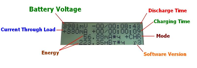
What information is shown on the display?
The display layout is quite useful. As far as can be understood from the images and description, the user can see several important pieces of information at the same time:
- Battery voltage
- Approximate current according to the selected load
- Discharge time
- Charging time
- Accumulated mAh value
- Accumulated mWh value
- Operating mode
- Software version
Since the time information is kept in day/hour:minute:second format, the display does not lose its meaning in long tests either. This is a useful detail especially in capacity tests performed at low current.
Button and LED functions
Multiple functions are handled with a single button on the device. A short press switches between charge and discharge modes. A double press selects the discharge load. A long press resets the counters of the active mode. This type of single-button control is a method frequently used in embedded systems, but it requires proper software.
The LED side is also kept simple. Fast blinking indicates discharge, slow blinking indicates charging, and steady on indicates that charging is complete. In this way, the basic status can be understood without looking at the screen.
The most important point in practice: accuracy and limits
This device is not a laboratory-type professional battery analyzer. The design approach does not force it to be one either. A device that can be built quickly, does the job, and gives results meaningful enough for real use was targeted. Therefore, some limitations should be known from the beginning.
First, since the current is not measured directly, the results depend on the actual values of the load resistors. As R3 and R4 heat up, their resistance may change slightly. Especially the 10 ohm and 20 ohm loads naturally heat up during long tests. Therefore, if better accuracy is desired, it makes sense to use resistors with low tolerance and a better temperature coefficient.
Second, the device terminates the battery test at a 2.7V cutoff. Although this value can be used for many single-cell lithium batteries, different termination values such as 3.0V or 2.8V may also be encountered in different sources. In other words, when comparing the capacity found with this device with other test devices, it is necessary to check whether the cutoff voltage is the same.
Third, the charging section is for single-cell lithium batteries. Due to the TC4056A-based structure, it is not suitable to use the device for multi-cell packs such as 2S or 3S.
Short notes about the components in the schematic
STM32F051K6 is an appropriate choice for this task. It offers the necessary peripherals such as ADC, timer, and I2C in a single package. Operating it with the internal oscillator keeps the circuit simple.
LM1117-3.0 is an easy solution for obtaining 3V with a small number of components. However, since the input is 5V and the output is 3V, some heat may be generated on the regulator. Since the consumption is low, no major problem is expected, but it should still be taken into account in very tight enclosures.
Using logic-level MOSFETs such as IRLML2502 for load switching is the right choice. Since they can be driven at around 3V, they can be controlled directly with STM32. IRLML6402 offers a suitable P-channel MOSFET solution for switching the charging path from the high side.
Things to pay attention to during assembly and use
- Do not select the load resistors randomly. Measurement accuracy is largely determined here.
- Do not underestimate the power rating of the resistors. Serious heating may occur especially during long tests.
- Do not use it with anything other than a single-cell battery. The structure designed for 1S Li-Ion and Li-Pol is not suitable for higher-voltage packs.
- Software modification may be required. If a different display, different microcontroller, or different load resistor will be used, the source code must be adjusted accordingly.
- Consider airflow inside the enclosure. During discharge, the load components and the MOSFET area may heat up.
Projects of this type are instructive not only for building a test device, but also for seeing ADC measurement, MOSFET switching, battery charge management, and embedded software together. For those interested in similar projects, electronic measuring instruments are also a good area of study.
General evaluation
This design offers a simple but smartly thought-out solution for seeing the real capacity of single-cell Li-Ion and Li-Pol batteries.
Its strongest points are that it combines charge and discharge in a single device, offers three different load options, displays the result as both mAh and mWh, and has a flexible software structure with STM32.
It can be described as a “weekend project” example that can be built quickly, is genuinely useful, and can be used continuously in the workshop.
Especially if you have many 18650 cells, such a device is very useful for sorting, matching, or testing them before using them in second-life projects.
Moreover, since the schematic is simple, it can later be improved by adding a current shunt or defining different cutoff levels in software if desired.
Source: cxem.net/izmer/izmer203.php


