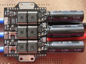
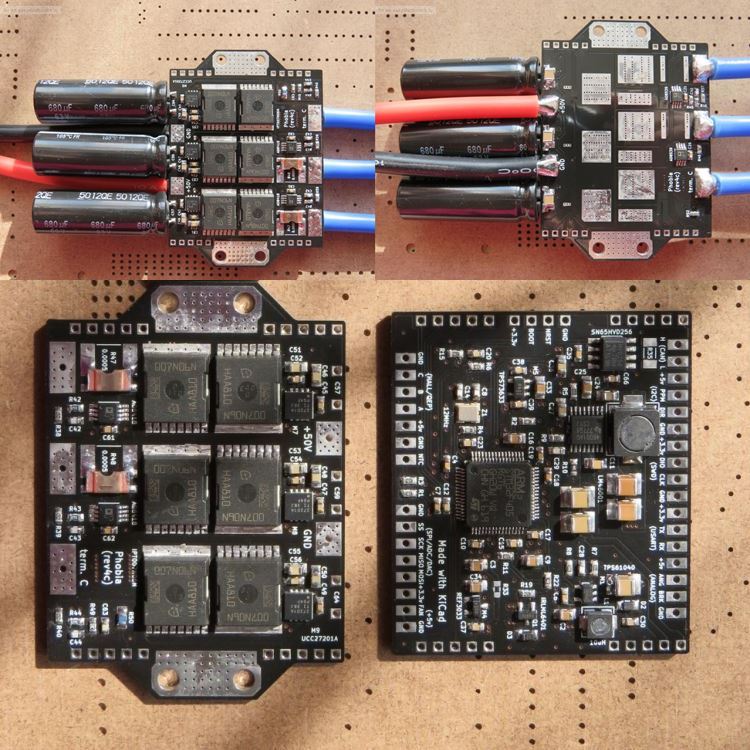
The BLDC motor control circuit based on the STM32F405RG has a highly developed design. All materials except power solids capacitors are in SMD type. Power Mosfets ipt007n06n is a difficult circuit design but it can be useful for similar projects. 8-layer PCB drawing file prepared with source code and Kicad was shared.
Sensorless vector control of PMSM based on two-row current measurement.
Advanced PWM to reduce switching losses and make full use of DC link voltage.
Fast and robust multiple hypothesis flux observer (MHFO) with gain planning.
Terminal voltage detection to reduce the effect of Dead Time.
Define automatic motor parameters without using additional tools.
Self test of hardware integrity to diagnose problems.
Flux attenuation control (EXPERIMENTAL).
Terminal voltage monitoring (EXPERIMENTAL) to start smoothly with the engine running.
Two-phase machine support (eg bipolar step) (EXPERIMENTAL).
Advanced command line interface (CLI) with autocomplete and history.
Noncritical tasks are managed by FreeRTOS.
Flash storage for all configurable parameters.
Working at low or zero speed:
Forced control that applies the current vector without feedback to force the rotor rotation.
High frequency injection (HFI) based on magnetic protrusion (EXPERIMENTAL).
Hall Sensors or Quadrature Encoder (TODO).
Control cycles:
Current control is always active.
Speed control loop.
Servo operation (EXPERIMENTAL).
Battery charger (TODO).
Voltage rectifier (TODO).
Adjustable limits:
Phase current (with adjustable drop from overheating).
Welding current (or power) consumption and renewal.
DC-link overvoltage and undervoltage.
Maximum speed and acceleration (as part of the speed control loop).
Control inputs:
CAN bus (TODO).
RC servo pulse width.
STEP / DIR (TODO).
Analogue input with brake signal.
Manual control with CLI.
The special embedded application can implement any control strategy.
Features of the V4C version;
Dimensions: 90x50x15 mm
Weight: 40g (2 art) 230g (with heatsink)
Supply voltage between 5v – 50v
Power up to 120A
Two analog inputs added (0 to 6v), Fan control output added (5v), Improved phase voltage measurement circuit (zero offset), True four-point trace of shunts (accuracy ~ 2%)
Limitation of current consumption added (just before power), DC link voltage limit added
Added a new position observer (winding resistance slip resistance) Calculation of consumed energy and distance traveled, Area weakening control added, Improved speed operation (up to ~ 0.05v EMF)
Testing: In a phase current of 120A, the card warmed up to ~ 85C for 20 minutes.
Source: we.easyelectronics.ru/my/amaora
FILE DOWNLOAD LINK LIST (in TXT format): LINKS-26564a.zip


Contrôleur de moteur BLDC STM32 ARM
Le circuit de commande du moteur BLDC basé sur le STM32F405RG a une conception très développée. Tous les matériaux à l’exception des condensateurs solides de puissance sont de type CMS. Power Mosfets ipt007n06n est une conception de circuit difficile, mais elle peut être utile pour des projets similaires. Fichier de dessin PCB à 8 couches préparé avec le code source et Kicad a été partagé.