A nice project implemented and shared by our member named H@S@N on the forum is a tested project, so it would be good to share it on the blog.
The car amplifier consists of 3 parts SG3525 (ka3525, kia3525, uc3525 are the same) smps circuit based on pwm control (EI35 Transformer) BJT Transistor amplifier circuit and original JBL filter circuit, thanks to my brother H@S@N for sharing, the following explanations belong to him.
boll
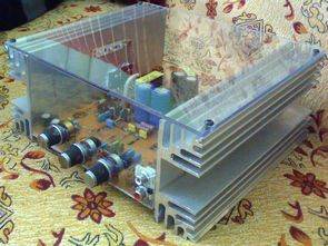
Hello masters. I would like to present to you the car amplifier circuit I made upon the request of a friend.
It has a 250 watt rms amplifier + smps + jbl filter. I used EI-35 instead of EI-33.. Connect the zener diode in the smps section to the maximum voltage you want. I also have a 75 volt zener diode. I got +75 / -75 volt voltage..
The coolers on it are for testing purposes… I tested the amplifier at 2 ohms. When I hit the bass, the power supply made a sound like welding 🙂 The gain of the jbl filter is very good. The circuit worked the first time without any problems.


Project Proteus ares of the pcb:


Subwoofer Filter 25Hz 250Hz Bass Crossover Circuit
Circuit quality quite a crossover frequencies between 250Hz 25Hz circuit board on the opamp 4558 setting can be made. Proteus ares of project drawings are printed circuit boards. Subwoofer Crossover @ ahmedyerli of circuit and PCB design