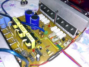
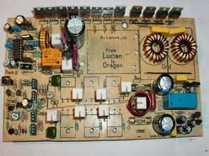
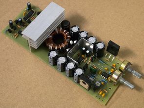
SG3525 Circuits SG3525 Projects SG3525 pulse width modulator PWM control integrated, can be used for the control of all kinds of switched power supply. High performance. A synchronization input to the oscillator allows multiple units to be supplied or a single unit to be synchronized to an external system clock. A wide range of dead time control can be performed with a single resistor connected between the Frequency and Discharge pins, plus a built-in soft start circuit set by an external timing capacitor.
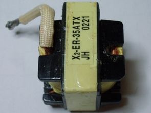
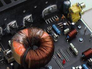
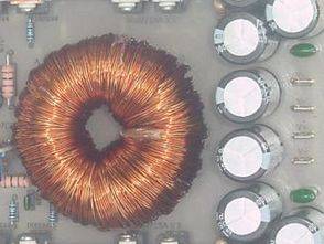
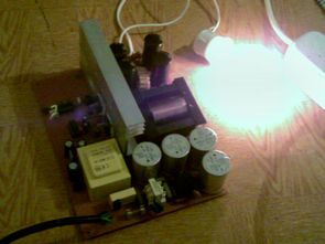
Transistor 2X100W stereo and mono bass amp circuits by converting 12V battery voltage (between 11v…14.4v) SG3525 DC DC voltage amplifier circuit to around 2X30…35V. There is protection against short-circuiting in both circuits and short-circuiting of the transistors at the amplifier output and giving DC voltage. The 120W subwoofer amplifier has an adjustable bass filter circuit
My brother Hasan is an old project of two channels 300w and 500w versions. Pre-shared 500W 250W Hi-Fi Transistor Amplifier Circuits and SG3525 EI33 ATX 200-600w DC-DC Converter for auto amplifier projects Output power transistors of the Amplifier Circuits 2SC5200, 2SA1943 DC DC converter floor SG3525 pwm control integration is used. EI33 transformers are used
Amplifier 4×60 Watts. To its solution was first selected integrated circuit LM3886T. The proposal continued the calculations and the election of the additional components of the integrated circuit and the design of printed circuit connections. To the end amplifier was also designed system of active cooling. In the fourth chapter was made the proposal of
Complete car amp in a project stk4131 amp solid-II solid KA3525A DC-DC converter (SG3525) is located in the Filter section based on the bass opampli also tl074 DC-DC converter, the primary windings of the transformer circuit used; 2×6 2x type 9 secondary species (connected in parallel with wire Section 2 1mm) of the circuit diagram
190W RMS output stage amplifier circuit PCB printed circuit design darlington transistors are used TIP142 TIP147 very good original Car where there is no difference. Darlington amplifier supply voltage of +-30v DC battery to translate the symmetrical SG3525 control IC izerine Board is used only in this episode and amp DCDC converter circuit on the
Now I think about it in my head a lot of trouble while this circuit how I applied stunned quite a time now , huh now ha then say a kind I have not shared this day kısmetmiş Anyway my point was very useful to practice a lot of experience earned now DC DC Converters
This car amp circuit one where I saw the original, but only there was a picture I think he of the amplifier clone anyway .. circuit of the amplifier on the floor 2 LM3886 is used used in car 12v battery voltage symmetric 2 × 40 volts to turn sg3525 based on the DC to
1400w 12v DC to DC converter circuit dc voltage converter circuit as symmetrical +-70V dc is turning sg3525 SMPS PWM control IC is used on the floor. In practice, the output transformer used optionally divided into two parts to meet more precisely 1400w power single core can also be used if nüvebulun. Primary and secondary
SMPS circuit have 3 version of the 700w (+-50v 50khz), 800w (+-42v 60khz) and 900w (+-70v 50khz) circuit diagrams for the same smps pwm control output is used to drive the integrated MOSFET sg3525 ir2110, but according to some of the values are different, the forces of the output of the SMPS circuit voltajlarına has
I also post a car amplifier, 100% own achievement. The amplifier consists of SMPS (switching source), SG3525 oscillator and 4 + 4 N-mos IRFZ48 and the amplifier is according to the “classic” N-mos 350 scheme with 6 IRFP240 endpoints. The transformer for SMPS is made of two smaller transformers recovered from an inverter, of which
Symmetrical power supply circuit 12v input voltage +350 V-350V integrated sg3525 used to control the PWM turns. Author Lamp amp is designed to run 350volt 400mA per channel output power, in addition to strong oladıkc +15 v and 78xx series regulator depending on downs. Dc to dc inverter circuit SMPS (switched mode power supply) works
Stereo auto amp project amplifier 2 for LM3886 for supply sg3525 used the converter input voltage 12v … 14.4 v between output and 2 × 30 volt transformer for the FT140/77 toroidal ring core (inner diameter of 0.9 outer diameter 1.4) used PROM winding three 1mm wire 2 × 5 connected in parallel to the
Forum @hasan is applied to a beautiful project that share our members apply the tested also be shared on the blog for a project that would be good. Car amplifier 3 main parts SG3525 ( ka3525 , kia3525 , uc3525 are the same) PWM control based on the SMPS circuit ( EI35 Transformer ) BJT
SMPS switch mode power supply circuit power amplifier used in the output symmetrical + – 50v 4N35 opto-coupler connected to the 10k potentiometer with a voltage adjustment can be done, of course, extremely high or low should not be set higher voltages for the output filter capacitor voltage must be increased and the transformer’s secondary
DC to DC converter PWM sg3525 SMPS control circuit transformer model based on integrated EE42/21/15 far as I know there was on the market. 4N35 opto feedback with Kubla made stable driver output MOSFETs IRFZ48 4 You can use it to run the amp 12 volt car battery voltage symmetrical + – raises to the