100W, 300W, and 500W transistor power amplifiers have been prepared with a similar logic. There are some differences in the circuit schematics, but they are designs that address different levels in terms of power stage capacity and power supply requirements.
The circuits generally have a classic power amplifier structure consisting of a small-signal input stage, a driver stage, and power transistors at the output.
The inclusion of details such as protection diodes, compensation capacitors, emitter resistors, and output coil in the schematics shows that the circuits were prepared not only to amplify sound, but also with more stable operation in mind.
100W amplifier circuit
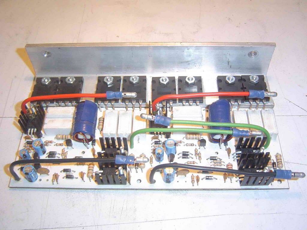
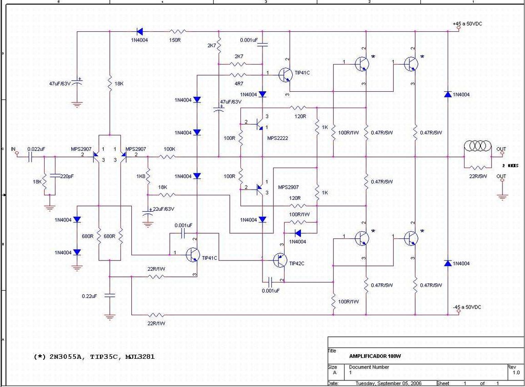
The 100W amplifier is a power amplifier that looks structurally simpler, but still requires a serious power supply and cooling.
Small-signal transistors are used in the input section, TIP41C and TIP42C are used on the driver side, and the power transistors indicated with an asterisk are used on the output side.
In the note section of the schematic, it is stated that transistors such as 2N3055A, TIP35C, or MJL3281 can be used for this section.
The low-value resistors seen on the emitter side in the schematic are important for balancing current sharing between the power transistors operating in parallel.
The coil and resistor network at the output helps the amplifier behave more stably, especially with difficult speaker loads.
In short, the circuit was prepared not only with the idea of “just producing sound”, but with the aim of more proper operation.
300W amplifier circuit


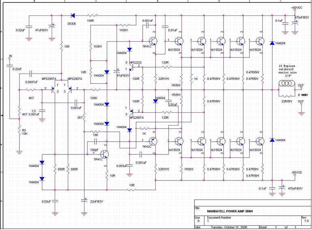
The 300W amplifier has a clearly more powerful structure compared to the first circuit.
In the schematic, multiple MJ15024 power transistors are used in parallel, and this design can be used under high current and heavier load conditions.
There are again TIP41C and TIP42C transistors in the driver stage. The more crowded output section naturally requires a larger heatsink, a stronger power supply, and more careful assembly.
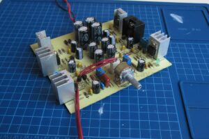
500W amplifier circuit
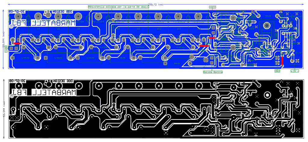
The 500W amplifier circuit also has a similar structure to the others, but there is no circuit schematic. The component values are written on the PCB top layout. The PCB design is quite small.
Source: forosdeelectronica.com/threads/diagramas-de-amplificadores.188450/page-104
“`