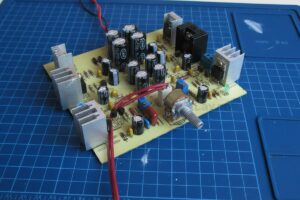
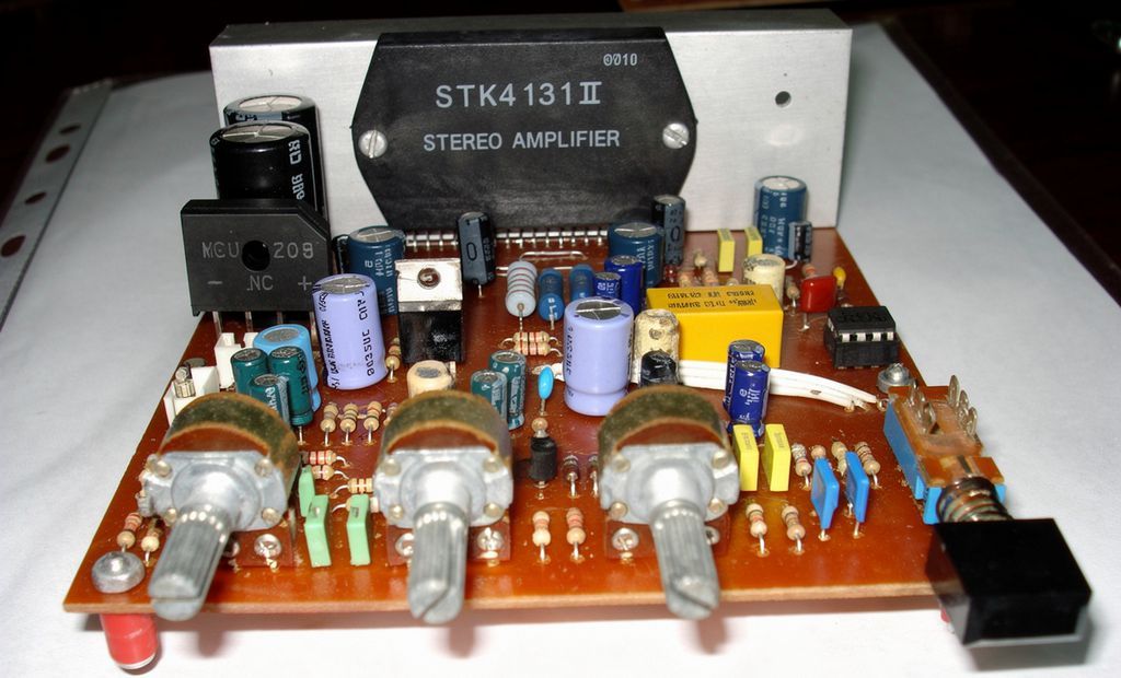
This stereo amplifier circuit built with STK4131-II is a practical audio amplifier solution that can be used at home, in a workshop, or in small workplaces. The circuit has an integrated structure that includes a 2x20W class hybrid power amplifier, a tone control stage with BC109C transistors, loudness support, and a speaker delay relay with a 555 IC.
The main goal in the design is to obtain a stereo amplifier that is not complex, is understandable, has a good cost-performance balance, and gives satisfactory results in real use.
This type of project is especially suitable for those who want to build their own STK amplifier circuits, those who are considering using their old speakers, or those who want to set up a simple stereo system for desktop use.
What is the STK4131-II IC?
Contents
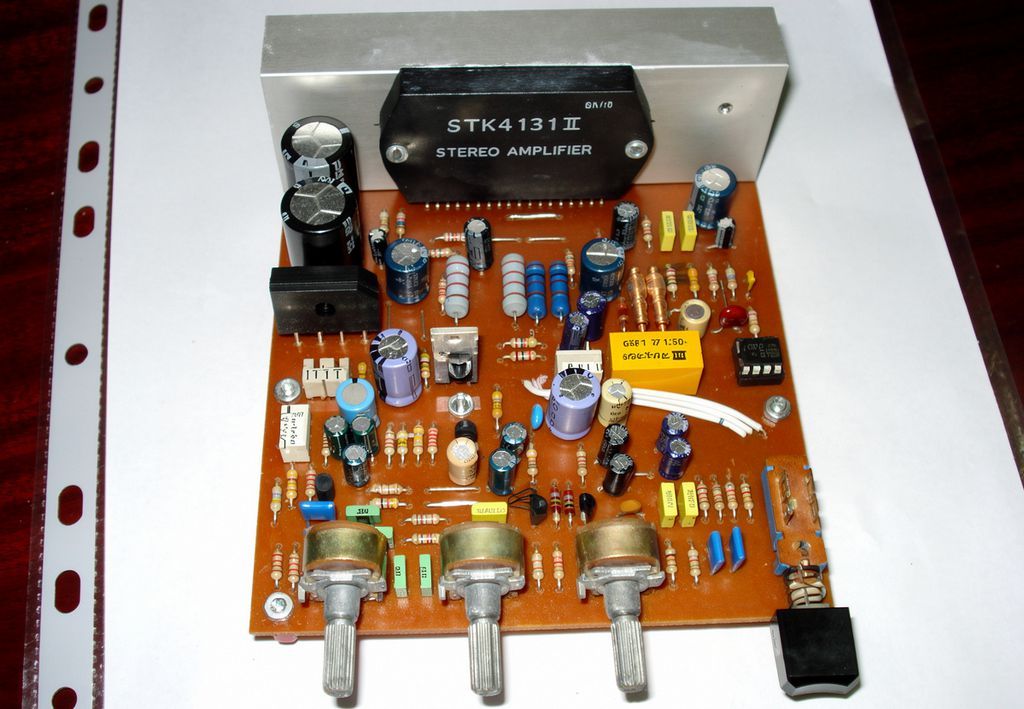
STK4131-II is a hybrid IC produced by Sanyo and designed as a two-channel audio power amplifier.
In the datasheet, this model is defined as a 2-channel 20W min AF power amp.
It is designed to be used with a ±23V supply and an 8 ohm speaker load under the recommended operating conditions.
The frequency characteristic is given in the 20Hz-50kHz range.
This makes it suitable for home music systems and small stereo applications.
These hybrid ICs offer a more organized setup with fewer components compared to classic amplifiers with discrete transistors.
They provide advantages especially in terms of ease of assembly, a more compact PCB design, and obtaining a working system in a shorter time.
General structure and operating principle of the circuit
In this project, while the STK4131-II is used as the power stage, there is a separate active tone control stage on the input side.
With the BC109C transistors seen in the additional circuit, bass and treble adjustments can be made.
Thus, the user can shape not only the volume level but also the sound character according to personal preference.
Some component values on the original circuit were changed, and some sections were rearranged according to the intended use.
With this arrangement, the aim was to make the bass and treble response more useful and the loudness effect more noticeable.
As a result, an application emerged that not only works, but also gives a more balanced and more enjoyable result during listening.
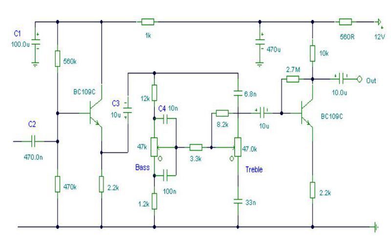
What does the tone control and loudness circuit do?
The tone control circuit shapes the frequency content before applying the input signal to the STK4131-II power stage.
Bass frequencies can be increased or reduced, and treble frequencies can also be adjusted in the same way.
This feature provides important advantages for different speaker boxes, different room acoustics, and different music genres.
Loudness is especially useful at low volume levels.
Since the human ear is less sensitive to bass and treble frequencies at low sound levels, loudness support helps the sound be perceived as fuller and livelier.
This feature is very useful so that music does not sound weak and lifeless when listening at low volume.
The point to be considered here is that the tone control and loudness circuit should not be added randomly.
Components selected with incorrect values can create excessive bass boost, muffled sound, or tiring treble.
For this reason, proceeding with tested values usually gives safer results.
Similarly, if preamplifier and tone control circuits are of interest, the input stage of this circuit can be examined as a good example.
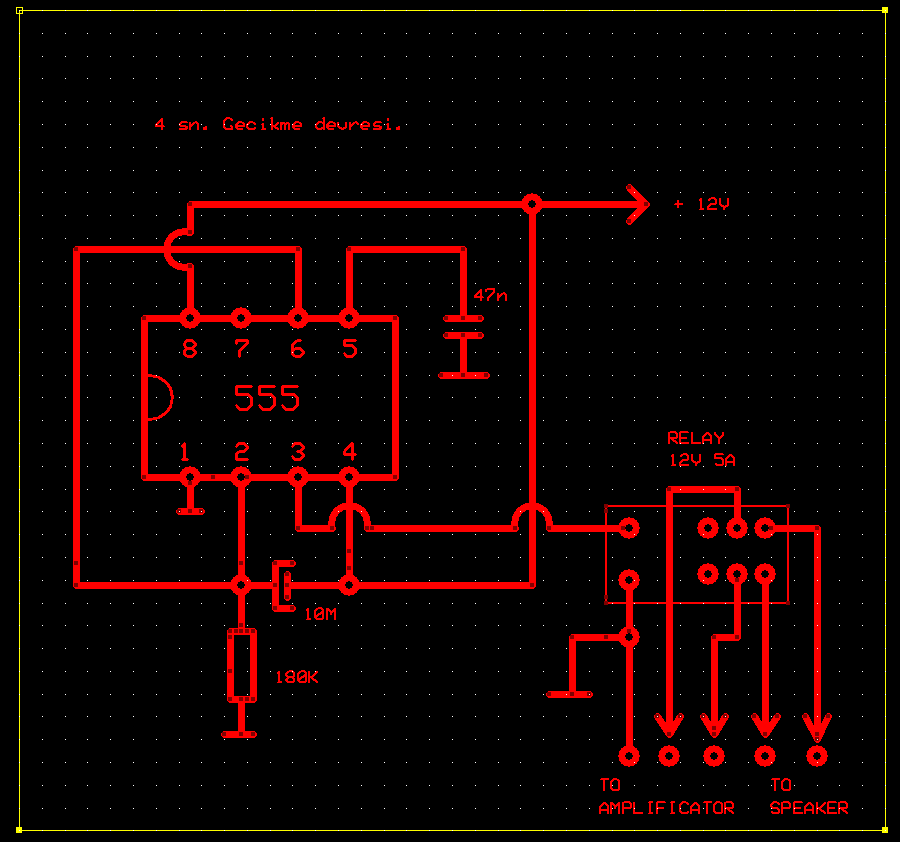
Why is a speaker delay circuit with 555 added?
One of the most common problems in amplifier circuits is the speaker thump sound at power-on and power-off.
Especially if the speaker is connected directly before the power stage becomes stable, an annoying pop, click, or impact sound may be heard from the speaker.
This situation is disturbing for the user and may also create an undesirable operating condition for the speaker in the long term.
In this project, a relay delay circuit prepared with a 555 timer IC is used to reduce this problem.
When the circuit is energized, the relay does not pull in immediately. First, a short waiting period occurs, and then the speaker output is activated.
Thus, the speaker is not connected before the power stage settles. This application is very useful especially in older type amplifier designs.
In addition, the relay delay circuit can also help reduce some unwanted transition effects that may occur when the amplifier is turned off.
For a more stable result, adding a reverse-parallel protection diode to the relay coil is a good practice.
Power supply circuit and transformer selection
In this application, a 60W 2x12V 2A transformer, a 4A bridge diode, and 2 pieces of 2200uF 25V filter capacitors are used for the power supply.
These values provide a sufficient and economical structure for home use.
It delivers performance that will satisfy most users at small-to-medium listening levels.
However, there is an important technical detail here: in the STK4131-II datasheet, the recommended supply voltage is at the ±23V level.
Therefore, the practical DC supply obtained with a 2x12VAC transformer will remain lower than the ideal conditions in the datasheet.
For this reason, although the circuit works very well, it should not be expected to reach the theoretical power value in the catalog exactly in every use.
If the filter capacitors used in the power supply section are increased, bass control and ripple suppression performance can be improved, especially at high volume levels.
Cooling, speaker selection and assembly recommendations
Although the STK4131-II has a hybrid structure, it is a power stage that can heat up seriously.
For this reason, a sufficiently large heatsink should be used, thermal paste should be applied between the IC and the heatsink, and mechanical assembly should be done properly.
If air circulation is weak in closed enclosures, the temperature will rise faster, so the cooling issue should not be neglected.
On the speaker side, an 8 ohm load is a safer choice and more suitable for the datasheet.
When speakers with lower impedance are used, the IC may be stressed more.
In addition, using shielded input cables, carefully making the ground connections between the tone control board and the power board, and keeping the magnetic field of the transformer away from the input circuit reduce the risk of hum.
On the PCB, high-current paths and low-level audio signal paths should be separated from each other as much as possible.
Especially if the input line, tone control circuit, and power supply paths are routed together in an unplanned way, background noise and interference may occur.
Source: eproje @poyrazoruc