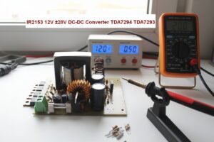
When audio amplifier ICs that operate with high supply voltage, such as TDA7294 and TDA7293, are intended to be used with a car battery or 12V source, the most important requirement is a suitable DC-DC converter circuit. Because these ICs cannot operate directly with 12V. The IR2153-based DC DC symmetrical power supply circuit is designed to operate TDA7294 and similar amplifier ICs with 12V DC.
The shared circuit is a compact DC DC converter designed to produce approximately +28V / GND / -28V output from a 12V input.
The main purpose is to obtain a suitable symmetrical power supply for TDA7294 or TDA7293 in vehicle environments or 12V powered systems.
Note: If you use IR2153D, you do not need to use a diode between pin 1 and pin 8.
IR2153 DC DC +- 28V
Contents
TDA7294 and similar class AB audio power amplifiers are different from simple car amplifier ICs that operate with 12V. They require a symmetrical power supply in order to obtain a higher output swing.
Therefore, instead of applying the 12V battery voltage directly to the IC, it must first be boosted.
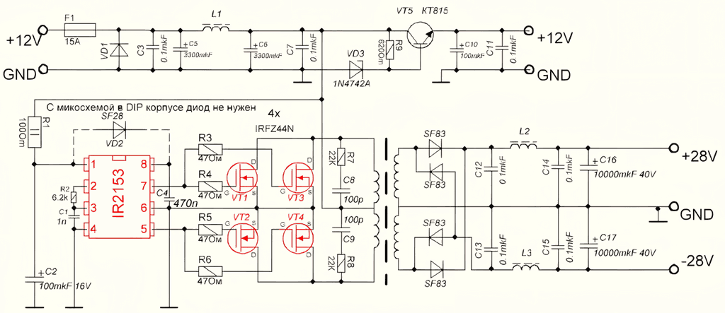
The circuit in the schematic does exactly this: it boosts the low DC input voltage and converts it into a bipolar supply suitable for the amplifier.
It is especially useful in in-car audio projects, portable powerful speaker systems, and transformerless compact amplifier designs.
Component List and Transformer Winding Information
- C1 = 1n
- C2 = 100mkF 16V
- C3 = 0.1mkF
- C4 = 470n
- C5 = 3300mkF 16V
- C6 = 3300mkF 16V
- C7 = 0.1mkF
- C8 = 100p
- C9 = 100pF
- C10 = 100mkF 16V
- C11 = 0.1mkF
- C12 = 0.1mkF
- C13 = 0.1mkF
- C14 = 0.1mkF
- C15 = 0.1mkF
- C16 = 10000mkF 40V
- C17 = 10000mkF 40V
- F1 = 15A
- R1 = 100Ω
- R2 = 6.2k
- R3 = 47Ω
- R4 = 47Ω
- R5 = 47Ω
- R6 = 47Ω
- R7 = 22К
- R8 = 22К
- R9 = 620Ω
- U = IR2153
- VD1 = SF83
- VD2 = SF28
- VD3 = 1N4742A
- VD4 = SF83
- VD5 = SF83
- VD6 = SF83
- VD7 = SF83
- VT1 = IRFZ44N
- VT2 = IRFZ44N
- VT3 = IRFZ44N
- VT4 = IRFZ44N
- VT5 = КT815
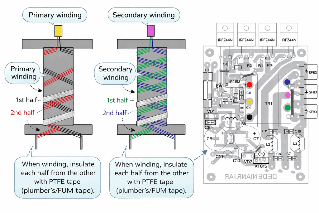
Transformer winding information
Primary 2×3 turns, 4x 0.75 mm; secondary 2×7 turns, 4 x 0.5 mm.
Input coil 5 x 0.75 mm, the others 5 x 0.5 mm…
Why was IR2153 preferred?
IR2153 is a practical SMPS control IC that combines the oscillator and driver stage in the same package.
For this reason, it becomes possible to drive MOSFETs and transfer energy through a ferrite transformer without setting up a very complex external control stage.
This is one of the important reasons why the circuit looks simple.
Especially for amateur and semi-professional applications, IR2153 is still a suitable IC for those who want to build a working structure without creating unnecessary complexity.
In the schematic, it can be seen that four IRFZ44N MOSFETs are used together with IR2153.
While these MOSFETs operate in the switching section, the energy transferred to the transformer primary is rectified and filtered on the secondary side with SF83 fast diodes to obtain a symmetrical output.
Since frequency selection, timing components, and core structure directly affect the result in this type of circuit, you can calculate the IR2153 frequency and access IR2153 datasheets from the SMPS IC operating frequency calculation page.
Building this DC DC circuit with IR2153 is easier than using ICs such as TL494, SG3525, etc. and requires fewer components, but it has no protection; actually, many of the others do not have it either (in many applications). Therefore, I recommend connecting a 5…6A fuse to the amplifier voltage inputs.
IR2153 DC DC Converter Details
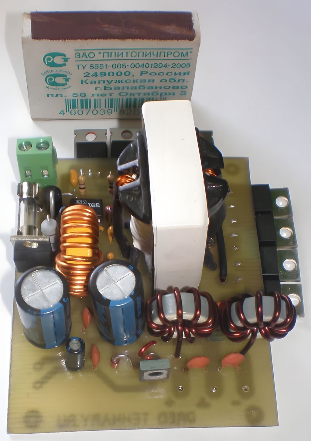
On the input side of the circuit, there are a fuse, filter capacitors, coil, and protection components.
This section is important so that fluctuations and sudden load changes coming from the vehicle electrical system cause less damage to the converter.
Although the protection and filtering components used at the input may look small, they are very useful especially in a vehicle environment.
In the main conversion section, the IR2153 driver and MOSFETs operate by switching the ferrite transformer.
On the secondary side, a cleaner symmetrical output is attempted to be obtained with fast rectifier diodes and an LC filter structure.
In the final section, large filter capacitors are used to create a power supply line that can respond more easily to the amplifier’s sudden current demands.
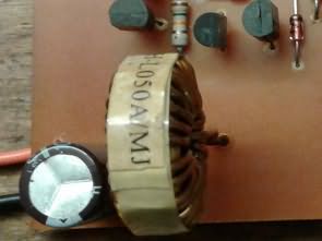
In the winding drawing in the schematic, it can be seen that the primary and secondary windings are arranged in a center-tapped structure. It is also an important detail that insulation between winding layers is recommended. In this type of converter, not only the connection schematic but also the transformer winding layout seriously affects the result. In other words, the success of the circuit is directly related not only to the electronic components, but also to the correct preparation of the magnetic component.
What should be considered when using it with TDA7294 and TDA7293?
The purpose of this power supply circuit is not to replace the amplifier board, but to power the amplifier board.
In other words, it tries to provide a clean and sufficient symmetrical source for the audio power stage to be built with TDA7294 or TDA7293.
Therefore, in the main amplifier circuit, proper cooling, mute/stand-by connections, short wiring, and good chassis ground layout should not be neglected.
Although ICs such as TDA7294 can provide high output power, the expected performance cannot be obtained if the power supply side is weak.
Especially insufficient transformer winding, thin PCB traces, low-quality capacitors, or poor cooling can lead to problems such as hum, voltage drop, entering protection mode, or MOSFET failure.
For this reason, the converter circuit and amplifier stage should be considered together.
In addition, in vehicle applications, battery cable thickness, vehicle chassis ground connection, and fuse selection are also important.
A circuit that works on paper may cause problems in real use due to faulty wiring.
Therefore, especially the high-current input line should be kept as short and solid as possible.
The PCB design of the TDA7294 IR2153 DC DC Converter circuit was prepared with Sprint Layout. There are 2 versions: one for using E ferrite core transformers of EI33, ERL, etc. type and one for using a toroidal ring core.
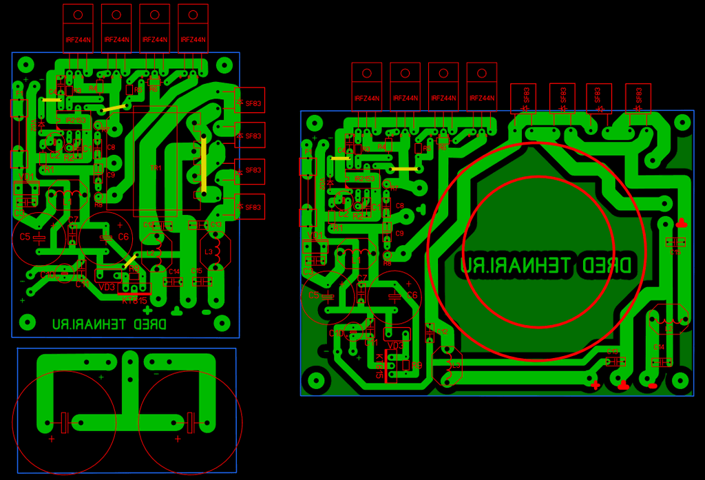
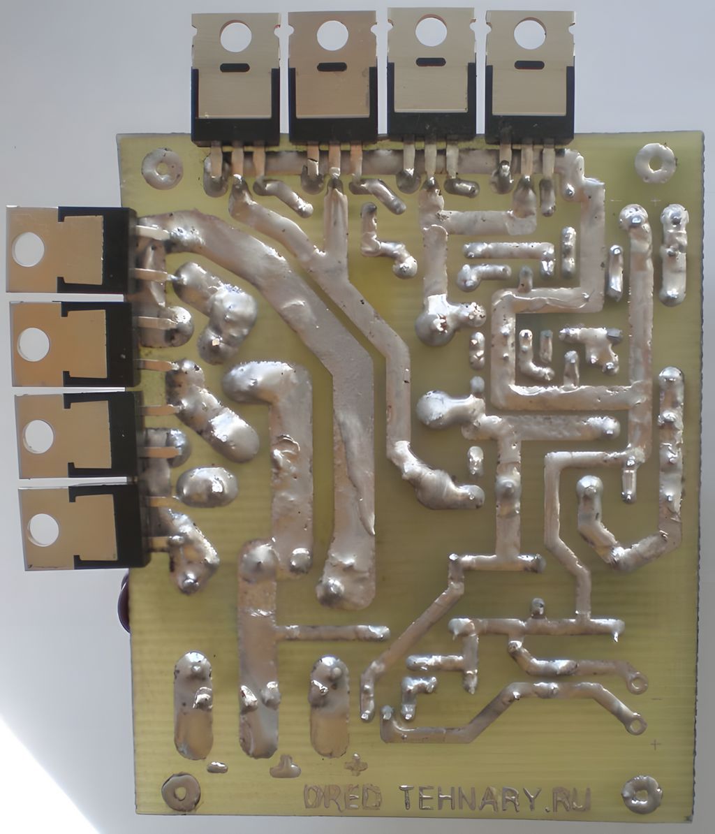
Source: tehnari.ru