An interesting project you know, this sort sd card input 7 inch image viewer (photo frame) fashion PIC24FJ64GA002 and nokia lcd using the mini image viewer made software c language yl crafted 16-bit dsPIC with çalıkş for people who are a good pic c example
Imaging for nokia 6100 LCD used but LCD direct PIC driven by the unknown additional driver integrated Used PCF8833 or Epson S1D15G00 can be ready-made modules sold in the application for yapam person, an additional circuit unfederated LCD module detailed information about the (software, data bits, etc..) Nokia 6100 LCD Display I do not know that the driver module is located in the market hopefully drivers are integrated.
In spite of everything dspıc24f and PIC C is a very good source for all sources. C and header files shared also eagle crafted with schematics and PCBs dosyalarıda there software aside from the most basic stock pcb drawing even could work a good design.
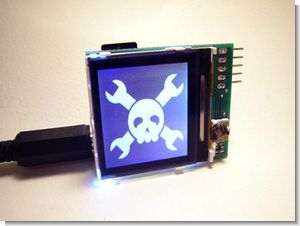
Digital Image frame Circuit Test

Bitmap images are stored on commonly used, PC-readable microSD cards. A PIC microcontroller reads images over the SPI bus. The PIC processes the image data and writes it to a color LCD over a one-way, 9-bit SPI-like bus. A configuration file on the SD card defines the delay between images.
DoDevre and PCB are designed using the free version of Cadsoft Eagle. In this project we used Microchip PIC24FJ64GA002 28pin SOIC microcontroller (IC1). We really like this chip because its peripheral pin selector allows us to put important features on the pins we want; this provides a smaller, simpler, more compact PCB. Each power pin has a 0.1uF bypass capacitor going to ground (C1,2). Internal 2.5 volt regulator requires 10uF tantalum capacitor (C12). The chip is programmed via SV1, a five-pin header. R1 is a pull-up resistor for the MCLR function on pin 1.
The 32.768kHz crystal (Q1) and two 27pF capacitors (C10,11) provide an oscillator for the real-time clock calendar (RTCC). These parts are optional, the initial firmware does not use them. RTCC can be used as part of a function that displays the current time on the screen. Buttons connected to the programming head can be used to set the time.
MicroSD cards are fully compatible with regular SD cards, microSD cards can be used in SD card reader/writer with an adapter. We tested several microSD card holders and settled on one from SparkFun Electronics. The microSD card requires a bypass capacitor between the power pin and ground (C3). An LED indicates microSD read activity, but is also useful for general debugging (LED1, R2).
This project is designed around SparkFun’s $20 color LCD panel. The LCD logic operates at 3.3 volts and requires a decoupling capacitor (C4). The LED backlight requires a separate 7 volt supply and appears to have a built-in current limiter as the example designs do not use external resistors.
The LCD has a separate input for the 3.3 volt display supply. Many report interference on the screen if this voltage is not clean. We used a ferrite bead (L1) and a 0.1uF capacitor (C5) to filter the feed and had no issues. This even worked on a dirty home-scraped prototype. Ferrite bead type doesn’t matter, we used one left over from our tiny webserver project.
The small connector is easy to solder on a professional board with a solder mask, but buy a few as fuses. SparkFun has a PCB footprint for this part in the Eagle parts library, but the spacing between pads is smaller than what Olimex or BatchPCB would produce. We glossed over by reducing the pad size to leave more space in between. Do not rely on the connector to hold the LCD in place, use tape to hold it in place. We used adhesive tape to temporarily attach the LCD.
A 3.3 volt supply supplied by the power supply LD1117S33 (IC2) powers the PIC, microSD card, LCD logic, and LCD display. The IC2 requires a 0.1 uF bypass capacitor (C6) on the supply side and a 10 uF capacitor (C13) on the output. We used the same tantalum capacitor we used for the PIC internal regulator.
The LCD backlight is powered by an LM317 adjustable regulator (IC3) configured to 7 volts with 240 (R5) and 1100 (R6) ohm resistors. C7 and C8 are 0.1uF bypass capacitors for the LM317.
J1 is an SMD power input for a common 2.1mm DC barrel plug. C11 is a 10uF electrolytic capacitor that smooths out any delay in the supply voltage. The C11 has a maximum input rating of 16 volts, so the supply voltage is best kept below 12 volts. 9-12 volts is probably the idea power supply range.
The firmware is written in C using the free demo version of the PIC C30 compiler. Learn all about working with this PIC in our introduction to the PIC 24F series. The firmware is in the project archive at the end of the article.
Microchip’s FAT 12/16/32 library provides easy access to files stored on SD cards. In a business card project, we made a detailed description of this library on our web server. If you have trouble reading a card with the library, check if the card was formatted in a digital camera or using Panasonic’s SD card formatter.
Nokia 6100 LCD driver
SparkFun has a basic 8-bit color driver (ZIP) for the Nokia 6100. We ported it to PIC and updated it for a 2 bytes per pixel 12 bit color mode. With a small amount of additional complexity, the pixel write speed can be easily increased by using a different 12-bit mode that provides two pixels using 3 bytes.
The LCD uses a 9-bit protocol, which is one bit more than most SPI hardware can handle. The first bit tells the LCD whether the next 8 bits are data or commands. Use the SPI peripheral to manually enter the first bit in the PIC 24F and then send the remaining 8 bits. It is impossible to be. We lose direct control of the pins when hardware SPI is enabled. Data input needs to be completely bit-busted, which significantly reduces the screen refresh rate.
source hackaday.com/ PIC24F SD Card Reader Circuit Image Frame Nokia 6100 LCD schematic pcb source code files alternative link


Analog Synthesizer Tone Generators Circuit
Circuit TL084, 555, CD40106 integrated based on the driver, b, fuzz, two band pass filter, tone genarate 1.2, LFO controls able modulation depth can be adjusted circuit supply 9-volt battery provided with further circuit schematic drawing in sections for different applications helpful may
Analog Sound Effect Circuit