It looks like a simple circuit, but you need to have some knowledge about PIC, the control of the circuit is done from the rs232 port on the computer.
There is a detailed explanation and source asm and hex code on the source site. I don’t know much about this subject, but it may be useful or enlightening to people dealing with PIC.
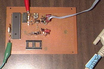
FODtrack Satellite Tracking Interface
Welcome to the biaxial rotor control interface page. Here is a low cost automatic antenna rotor controller developed specifically for amateur radio satellite tracking operations. The construction of this rotor control interface is quite simple. The circuit consists of only one PIC 16F877 microcontroller IC and several transistor drivers. Please take a moment and look around. You may find something useful!
Satellite tracking is most commonly done on a computer with satellite tracking software. The software FODtrack (by XQ2FOD) that I tried with this control interface can be downloaded from www.amsat.org. It uses the serial (COM) port (baud 1200) on your PC to drive external azimuth and elevation rotors to position the antenna via the interface described here. The data format of the GS-232 output command from the COM port is as follows:
Wxxx is yyy, where xxx is the azimuth and yyy is the elevation angle. The GS-232 command received via the PIC16F877 uart serial port is converted and stored in the on-chip ram area of the microcontroller as 8-bit binary azimuth and elevation target position values. Analog input signals from the position feedback pots of the rotators (0 to 5 volts for 0 to 360 degrees azimuth, 0 to 2.5 volts for 0 to 180 degrees elevation) are converted to binary values by the on-chip ADC and these are then compared. target position values to produce outputs to control up, down and left, right switches.
Assembler software to program PIC16F877 can be downloaded from www.microchip.com and P16PRO printer port PIC eprom programming software can be downloaded from www.picallw.com.
PIC16F877 microcontroller uart serial port baud rate is 1200 and crystal clock frequency is 10 MHz. The two-axis (azimuth and elevation) rotor drive output pins are RB1, RB2, RB4, and RB5. The rotor position is analog input pins AN0/RA0 and AN1/RA1.
Satellite Tracking Interface

Control schematic Satellite Antenna with PIC16F877 pic assembly source code alternative link:


VCF 24dB Mixer Circuit LM13700
LM13700 24 dB mixer circuit, TL082, TL084 op-amp based upon + – .15 9 have been working with PCB panel cizimi schema files and a detailed description has
Four Pole 24dB Per Octave Low Pass Filter
Log Response to Control Voltage (1V/Oct Tunable)
Makes A Nice Sine Wave Oscillator
Power Supply Range +/-9V up to +/-15V
Voltage Controlled Cut-Off Frequency
Voltage Controlled Resonance