Circuit LM13700, TL082, TL084 based on opamps working with +- 9..15v panel drawing pcb schematic files and detailed explanation (in English)
Features
Four Poles 24dB Per Octave Low Pass Filter
Log Response to Control Voltage (1V/Oct Adjustable)
Makes a Nice Sine Wave Oscillator
Power Supply Range +/-9V to +/-15V
Voltage Controlled Cutoff Frequency
Voltage Controlled Resonance
Looking for a great prebuilt filter module?
Synthasonic can help. Synthasonic produces fully built modules for this project. So if you like do it yourself but if you like do it yourself in a much more comfortable way…

Voltage Controlled Filters are in my opinion one of the coolest modules in any synthesizer. They can remove or add harmonics from the original signal and dynamically change the harmonic content as they are swept away by external control voltages or follow the keyboard voltage used to control your oscillators. I like the sound of a few oscillators tuned low and close to the accordion, passed through a low-pass filter with a fair amount of resonance.
When you modulate the cutoff frequency (also in the low range), you get the sound of an airplane flying overhead or a homy singer’s voice modulating the frequency content of her buzzing chants through formative filtering from the mouth and throat. And of course, white noise passing through a slowly modulated resonant filter makes it sound like you’re in the frozen tundra. This filter contains voltage-controlled cutoff frequency and resonance (or Q) that gives you more variables to play with as you experiment with sounds from your imagination. Additionally, it provides inputs for a three-signal mixer.
This is an intermediate to advanced project and I don’t recommend it as a first project if you’re just starting out with synths or electronics. Here only the circuit and some explanations are shown. Many project creation experience and knowledge of electronics and equipment ownership (scope, meters, etc.) come naturally.
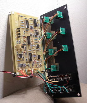
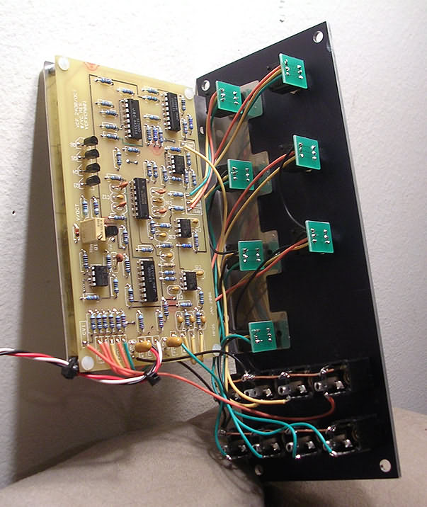
VCF uses LM13700 transconductance amplifiers as voltage controlled ICs. There are four in a chain and they work just as well. The conductivity of U2-B is controlled by the current flowing from R18 to Q3 to earth. It acts as a voltage controlled resistor with an RC filter in conjunction with C2. Since the output of U2-B is a current, the signal is actually integrated into C2. The filtered (actually integrated) signal is buffered by U4-B and fed to the next stage (plus a portion is fed back to the U2-B input via R26).
R14 is used to drive the LM13700 linearization diodes (introduced to reduce distortion through the amp). R52 compensates for the positive offset applied via R14 (yes it goes to -12 but the inverter is applied to the input). The goal is to keep the system’s signal path as close to ground work as possible. In practice you will see offset as high as +/-200 to +/-300 mV on any output of the U4, but that’s fine. If things were running near the tracks we would have a problem. The output is finally capacitively coupled to the output so the output signal works exactly around the ground.
Source: musicfromouterspace.com/ VCF 24dB Mixer Circuit LM13700 alternative link:


RMS 100W Mosfet Amplifier Circuit
100W amplifier Circuit with Speaker 8Ω 4Ω speaker with 100w rms 200w rms gives you the power supply voltage MOSFETs used from 2x32v 2x40v 4x 4x IRFP360 IRF540
100W rms amplifier 8 ohms or 4 ohms at 200Wrms MOSFET transistors. This amp was published in Elektor.the scheme and the typon to be able to adapt MOS transistors in housing TOP3 or TO220. The advantage of this amplifier is that it uses only N-channel MOS transistors for power. In addition, it is protected against heat-and short-circuits. It is possible to increase the power by multiplying the number of transistors MOS power.