stepper motor drive circuit diagram ccs c code hex “check-16F877 pic stepper-motor control can be made back and forth provided with 2 × 16 LCD 12volt driver steps on the screen you can see the details bc548 transistors used in section
CCS C Stepper Motor Driver

PIC16F877 Stepper Motor Driver Circuit CCS C Project details code and proteus files
PIC16F877 Stepper Motor Driver Circuit CCS C ZIP File Password: 320volt.com


Audio Signal Measurement Digital Millivolts Meter Circuit PIC16F88
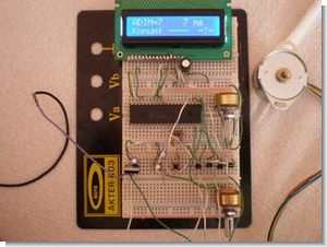
Millivolts meter circuit PIC16F88 based on 2 × 16 LCD display there mV, DBV, dBm signal levels can show audio signal input section ad623 and ad8307 used 12-15volt DC adapter operated on supply input LM317 regulated with built pic software assembly prepared by the asm hex placement There are plans pcb files
Input Impedance: 100kω (up to 600Ω balanced input) changed Frequency Measuring Range: 5Hz to 100kHz below, so above Maximum Signal Input Level: 1.4V RMS (DBV 3.0, 5.2 dbm/600ω)
At least Signal Input Level: 160μv RMS (-76dbv, -73.8dbm/600ω) Measuring Linearity: ± 0.3dB about Measurement Accuracy: ± 3% to about Power requirements: 12-15V DC <200 mA with LCD
PIC16F88 Millivolts Meter Project