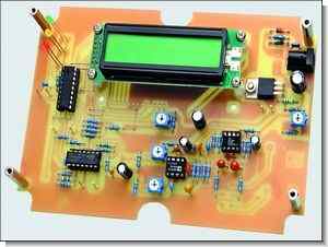
Milli volt meter circuit based on pic16f88 has 2×16 LCD display. It can show mV, DBV, dBm signal levels. AD623 and AD8307 are used in the audio signal input section. It can be operated with 12-15volt dc adapter. At the supply input, regulated with lm317, pic software is prepared with assembly, asm hex layout plan pcb files.
Input Impedance: 100kω (up to 600Ω balanced input) changed Frequency Measuring Range: 5Hz to 100kHz below, so above Maximum Signal Input Level: 1.4V RMS (DBV 3.0, 5.2 dbm/600ω)
At least Signal Input Level: 160μv RMS (-76dbv, -73.8dbm/600ω) Measuring Linearity: ± 0.3dB about Measurement Accuracy: ± 3% to about Power requirements: 12-15V DC <200 mA with LCD
PIC16F88 Millivolts Meter Project

Digital Audio Millivoltmeter. Versatile unit displays signal levels in mV, dBv and dbm
Do you want to measure small signals at audio frequencies? Here is a low cost digital audio millivoltmeter that will allow you to measure audio signals from below 5Hz to above 100kHz. In addition to displaying the level in both millivolts and dBV, it also displays the corresponding dBm level in 600 ohms.
Main Features: a low cost audio millivoltmeter based on a logarithmic amplifier/detector connected to a digital measurement circuit using a programmed PIC microcontroller and an LCD readout.
Input Impedance: 100kΩ (balanced input can be changed to 600Ω)
Measurement Frequency Range: below 5Hz to above 100kHz
• Maximum Input Signal Level: 1.4V RMS (+3, 0dBV, +5, 2dBm / 600Ω)
Minimum Input Signal Level: 160μV RMS (-76dBV, -73, 8dBm / 600Ω)
Measurement Linearity: approx. ±0.3dB
Measurement Accuracy: approx. ±3%
Power requirements: 12-15V DC at 200mA with backlit LCD
Block diagram of the Digital Audio Millivoltmeter. The audio signal is first fed to an impedance transformer stage (IC1) and then via a resistive attenuator to a log amplifier/detector. Its output is then fed to three different DC amplifiers that feed a digital voltmeter stage based on the PIC microcontroller IC4 and an LCD module.
We combined one of these Analog Devices AD8307 chips with an instrumentation amplifier to provide high input impedance and also added an “intelligent” measurement circuit based on a PIC microcontroller. During operation, the PIC processes the detector’s logarithmic DC output voltage to indicate the signal level and equivalent dBV and dBm levels.
The PIC micro uses some pretty fancy math routines to calculate the signal level, which is then displayed on a standard 2-line LCD screen. All circuits are on a single PC board and fit in a compact die-cast aluminum enclosure. The entire setup is powered from an external 12V battery or plug pack and draws less than 200mA (drawn by the backlight on most LCD modules).
The output of the impedance transformer stage is then fed through the 10:1 resistive attenuator to the AD8307 log amplifier/detector (IC2). This attenuator consists of 5kΩ resistors in series with each input and the AD8307’s own 1100Ω input resistor.
The output of the log amp/detector is essentially a DC voltage with a value closely proportional to the logarithm of the AC input voltage. In fact, the slope of the detector’s output is very close to 25mV per decibel increase or decrease at the input. By adjusting the load resistance of the log detector with the trimpot VR1, we can set the slope to 20mV/dB (for calibration).
Source: http://www.siliconchip.com.au/cms/A_111191/article.html
Audio Signal Measurement Digital Millivolts Meter Circuit PIC16F88 schematic pcb an soruce code files alternative link


USB Printer Sharing Switch Circuit
Between two computers commutator to be used with the printer will activate able which channel is active with LEDs can be seen loop supply does not require the LEDs USB Poarta chi 5Volt works with circuit 1/1 can be printed as PDFs formay the PCB drawing there
USB Printer Sharing Switch