Previously PIC16F628 and a similar share had been made in this project is more or less there used microcontroller pic16f627 3 pieces 220v 40w 60w can be used MOC3020 Optodiyak isolation from the provided pic Supply 6 volt transformer made by this way the system is isolated load is used to control Triac BT137 circuit diagram detailed description and the source code there. RC5 protocol is used for the control circuit controls
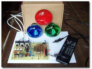
This RGB light I designed and built a while ago. A large spectrum of coloured light can be made mixing light from bulbs coloured in red, green and blue. So, this one is not based on LEDs but it’s based on 3×60W 220/110Vac light bulbs. Also, it has a remote controller to change intensity of the three bulbs, store and recall preferred hues, turn the thing on and off.
Danger !Before attempting to work on this project yourself you must be absolutely aware that this thing is powered from the mains and as such it could kill you, cause damage or injuries. If you are not very well skilled with mains powered electronics and related safety building practice and you are not well aware of the risks related, you are absolutely required just to enjoy the pictures and the video or get assistance by a very skilled friend.
No part of the circuit can be considered safe to touch when the circuit is powered on. This project is intended only for very experienced adults.
PIC16F827 RGB Light

The author of this document is not responsible for any death, injury, or property damage resulting from or relating to the procedures shown or devices described in this document. The bulbs: I looked for both 40W and 60W bulbs and found them from Philips and Osram. They are reasonably priced (4/5 Euro) and provide pretty good a spot of light so that the three beams can be superimposed and the three colours mixed. Other light bulbs could do well. They must be filament types, no ballasts or fluorescent tube, just good old filament types.
Dimming the lights cannot be done via PWM as LEDs are. The lamps must be phase controlled, that is they must be turned on with a delay with respect to the zero crossing of the mains phase. The delay ranges from 0 (no delay, lamp immediately turned on -> maximum light) to 1/2 of the mains period (20ms for 50Hz, 17 ms circa for 60Hz -> minimum light, dark). In the pictures below, the light intensity is strictly related to the area enclosed by the X axis and the curve. Top trace shows the mains, the lower one is the output to the green lamp (green light visible on wall in the background)
Driving the bulbs is done via TRIACs. They are cheap and well proven. Some RC network is necessary to reduce interferences produced by triggering of the TRIACs. The filter should be compliant so as not to disturb any electronic device around. The filters provided reduce interference pretty much but I have no idea if FCC or other regulations are really met.
Notice the heat sinks: they should not really be necessary as long as TRIACs are loaded with 60W each. But heat sinks look cool. Remember consider any part of the circuit dangerous when powered on: do not touch any part of it (to check for heat, as an example…) under any circumstances. No part of the circuit is safe to touch to anyone. And I mean you !Optocoupler
Safety first: Optocouplers provide isolation between low voltage (safe) side and high voltage(the mains) side. The low voltage side is connected internally to an LED facing an opto sensitive device (OPTODIAC) which is connected to the high voltage side. Lighting the LED makes the OPTODIAC conduct and trigger the TRIAC wich in turn turns on the lamp.
The low voltage and high voltage sides must be well separated electrically so has to guarantee isolation. The minimum requirement is to Dremel out the copper between the two sides. A much better practice is to dig a hole between the two side. For no reason interconnection should pass between the two sides.
The circuit must be powered via a low power transformer. This provides the added feature of isolation from the mains. As I said, isolation is a safety feature no one should underestimate. Even though the circuit does not have any pushbutton which might break and let electrical contacts become touchable by a hand and the circuit can be safely enclosed in an all-plastic case (special care must be taken for metallic screws), the transformer and the OPTODIACS provide added safety.

The IR receiver was taken from a dead TV set together with its remote control. The case is metallic and it is connected to the low power ground. Even if there is isolation, take precautions so as no metallic part (IR case also) can be touched. A transparent plastic for the circuit case would help.The controller is a PIC16F627A which receives the remote control signals. The software attached is commented and should be easily understandable by those who have some understanding of PIC assembler.
I tested the thing with 220Vac 50Hz. Could not test it against 110Vac 60Hz. The only difference relates to the transformer and the delay generating routine inside the micro (and the light bulbs ratings). Selection between 50Hz vs 60Hz timing is done connecting shown pin to ground for 60Hz.
CAUTION 220 volt RGB Lamp Control works with high voltage. Be careful, pay attention to the capacitor connections. If you reverse the + – poles, there may be large explosions at high voltage. Before operating the circuit, use the Fused Power Line, protective glasses.
source http://www.5volt.eu/archives/category/ isolated PIC16F827 RGB Lamp 220V control circuit diagram. pic Asm,. Hex files:


PIC16F876 PWM Fan Speed Control
PIC16F876 with PWM applications can be an example of a project 9 fans can be controlled 3 BUZ72 Mosfet with the PIC outputs reinforced LM60 temperature sensor information from the relative speed is changing the R and G LEDs with temperature condition can be observed CC5X prepared with the C source and hex code, circuit diagrams, there
Note: before programming (erasing) a 16F676 device, first read its CONFIG register and its last (0x3ff) program word! These contain factory-programmed calibration values, that become lost by (re-)programming! 1st sample: read last program word=343C config:’bandgap midhigh’