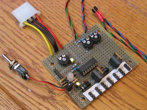
PIC16F876 with PWM applications can be an example of a project 9 fans can be controlled 3 BUZ72 Mosfet with the PIC outputs reinforced LM60 temperature sensor information from the relative speed is changing the R and G LEDs with temperature condition can be observed CC5X prepared with the C source and hex code, circuit diagrams, there
Note: before programming (erasing) a 16F676 device, first read its CONFIG register and its last (0x3ff) program word! These contain factory-programmed calibration values, that become lost by (re-)programming! 1st sample: read last program word=343C config:’bandgap midhigh’
Operation:
TMR0 is used to count up, driven by the internal oscillator.
In ‘set_fans()’ the counter value is compared with target values
to create PWM output signals.
Four analog inputs are sampled: three LM60 temperature sensors
and one ‘minimum fan speed’ setting.
At TMR0 wrap-around all PWM outputs are activated and a limited
amount of computation is done. During the TMR0 loop, the PWM
outputs are reset one-by-one.
The PWM frequency can be adjusted with the TMR0 prescaler,
typically between 64 and 512 Hz.
A global ‘time’ is maintained for a slow reduction of fan speed,
avoiding control loop instability. Note that this notion of time
floats with the TMR0 prescaler.
The PIC16F676 performs A-to-D conversion on the 4 analog inputs, and creates a PWM output signal to drive the fans. Besides 3 temperature values, one for each group of fans, it samples a value for a shared minimum fan speed setting. On rising temperatures, the fan speed rises linearly and immediatly. On decreasing temperatures, the fan speed decreases only very slowly, to avoid control instability: from 100% to 0 speed in about 8 minutes. Lowest temp setting (turn left): 20 to 30 degrees celcius results in 0 to 100% fan speed. Highest temp setting (turn right): 65 to 80 degrees celcius results in 0 to 100% fan speed.


80M Transceiver SSB-CW LA1185
I’ve made a few changes to the design of the transceiver. Changed the layout of the printed on the plate. Dodalem emisje CW. I added the emissions CW. Pressing PTT microphone transmitter runs in the SSB mode, pressing the key forces CW emissions at the same time blocking the track microphone. If you plan to construct a device SSB skip the numbers from 1 to 99 For the CW must be fully fill the plate and in addition, do less, for which there is a temporary arrangement remains uncovered broadcasting BK together with the control block, built on a CMOS system in 4093 and monitor broadcasting.