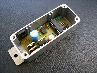
The pwm method is used in the motor control circuit, the microchip product tc4420 high speed 6 amp mosfet driver is used at the output of the pic16f819, while the mosfets are 2 pieces irf2907. There is also a current detection circuit over a 0.01ohm shunt resistor made with a tlv2461 op amp to detect the current drawn from the mosfets. There are source picc codes, pcb, schema files of the Pwm Motor driver project.
An electronic speed controller for my electric bike. As you can see here, I’ve been traveling by electric-assisted bike for a while. I bought a standard bike that I equipped with the kit (hub motor and battery). I could have bought a complete kit with the controller, but I chose to do it myself for the sport and to be able to integrate interesting functions that are not available in the controller supplied with these kits.

The hub motor used is a brush motor purchased from Velectris. I chose a brushed motor because it only has 2 wires and is easier to drive. The flip side of the coin is that the motor is slightly larger and above all has lower efficiency than a brushless motor.
The motor runs at 36 V with a 14 Ah lithium battery. The purpose of the controller is to be able to fine-tune the engine power using an accelerator. To do this, we will cut off the battery voltage so that we can send an average voltage between 0 and 36V to the motor. This is called PWM (Pulse Width Modulation) control.
The heart of the controller is a PIC microcontroller, the PIC16F819. It has everything we would need internally, including a PWM output and analog inputs. Moreover, it is very economical.
The power supply is based on a standard LM7805 linear regulator. A zener diode does the job of lowering the input voltage because the regulator does not directly accept 36V from the battery (42V even when fully charged!).
Measurement of battery voltage is performed using a simple voltage divider up to 10 and the analog input of the PIC.
Motor power control is done using MOS transistors. I put the 2 in parallel to reduce the total internal resistance and the power to be dissipated (especially the losses from switching), but ultimately a single MOS is sufficient if well chosen.

The PIC can only output a few milliamps at its outputs and cannot directly drive the MOS gate at the switching frequency to be used (around 8khz). Indeed, the MOS gate acts like a small capacitor that needs to be charged and discharged every time it is switched. And this must be done as quickly as possible so that the MOS works as fully as possible to limit losses and therefore overheating. That’s why I placed a special component, the TC4420, between the PIC and the MOS gate. It will be able to provide the current required to drive the MOS gate. If you do not want to blow up the MOS due to overvoltages caused by the motor windings, you will have noticed the presence of a free diode at the motor terminals.
I am using a 10 milliohm shunt to measure the current drawn by the battery. An amplifier with a gain of 10 returns the signal to a value that can be measured by the PIC. AOPs always have waste voltage near their supply voltage (0V and 5V in this case), I added an offset to the input thanks to the R7 resistor.
For example, if no current flows through the shunt, the voltage across the shunt is 0V. The + input of the AOP will therefore (10K/(10K+490K))*5V = 0.1V.
Since the gain of the amp is 10, we will get 1V output.
If a current of 20A flows through the shunt, the voltage across it will be 0.2V (U=RxI=0.01×20).
The + input of the AOP will therefore have (10K/(10K+490K))*(5V-0.2V)+0.2V = 0.296V. With a gain of 10, we will have an output of 2.96V.
However, it is necessary to choose an AOP that accepts input and can provide output voltages close to the power supply. These are called rail-to-rail AOPs.
I provided 3 identical analog inputs to connect the accelerator. The signal is simply filtered by an RC low pass filter. Currently only one will be used, but in the future if I want to connect for example a pedaling sensor or something else, I will have 2 free.
Note: There is a minor error in the schematic: R5 must be BEFORE the MOS driver and therefore must be connected between the ‘PWM’ signal and ground. Maybe one day I will change the schema and routing…
PWM Electronic Bike Motor Driver
The heart of the controller is a PIC microcontroller, the PIC16F819 It has internally everything we will need, including a PWM output, and analog inputs. it is very economical.
The is based on a standard linear regulator LM7805. A zener diode is responsible for lower input voltage, as the regulator would not accept directly from the battery 36V (42V even when it is loaded block)
Measuring the battery voltage is done through a simple voltage divider by 10 and an analog input of the PIC.
Source: chaenel.free.fr Electric Bike Motor Control Circuit pcb schematic pic c source code alternative link:


PIC16F84 Simple LED Blink PIC-C
In this project, I PIC16F84A microcontroller PORTB bits to 0 (RB0) LED (light emitting diode) is connected. In the project, this LED is extinguished and burned at intervals of 250 milliseconds. was operated with a 4MHz crystal microcontroller. RB0 port (pin 6) is connected to a resistor and an LED.
PIC16F84 LED Blink Schematic