Normally, I don’t share projects that only have hex code without source code, but this is an exception, a different project. Sound system Surround, remote control, 2×16 LCD display (tone, temperature, etc.). Although I shared a similar circuit made with a transformer before, I made a symmetrical smps circuit with IR2153, this circuit is a single source between 12..14v volts.
As I said, asm or whatever language it is written in, there is no source code, you can use it with hex code. It can inspire people who want to add Microprocessors to their sound systems.
IR2151 Switch mode power supply SMPS

A modern amplifier, as a rule, is a combination of several units: switching and display units, volume, tone and balance controls (equalizers), power amplifier. This is due to the fact that the functional saturation of modern equipment is constantly increasing, and it is much easier to design and manufacture each unit separately. This makes it easy to combine and replace individual units. Installation is greatly simplified. In addition, the problem of amplifying the amplifier is easily solved.
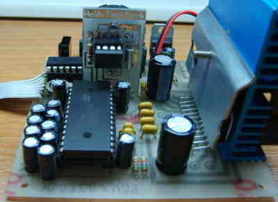
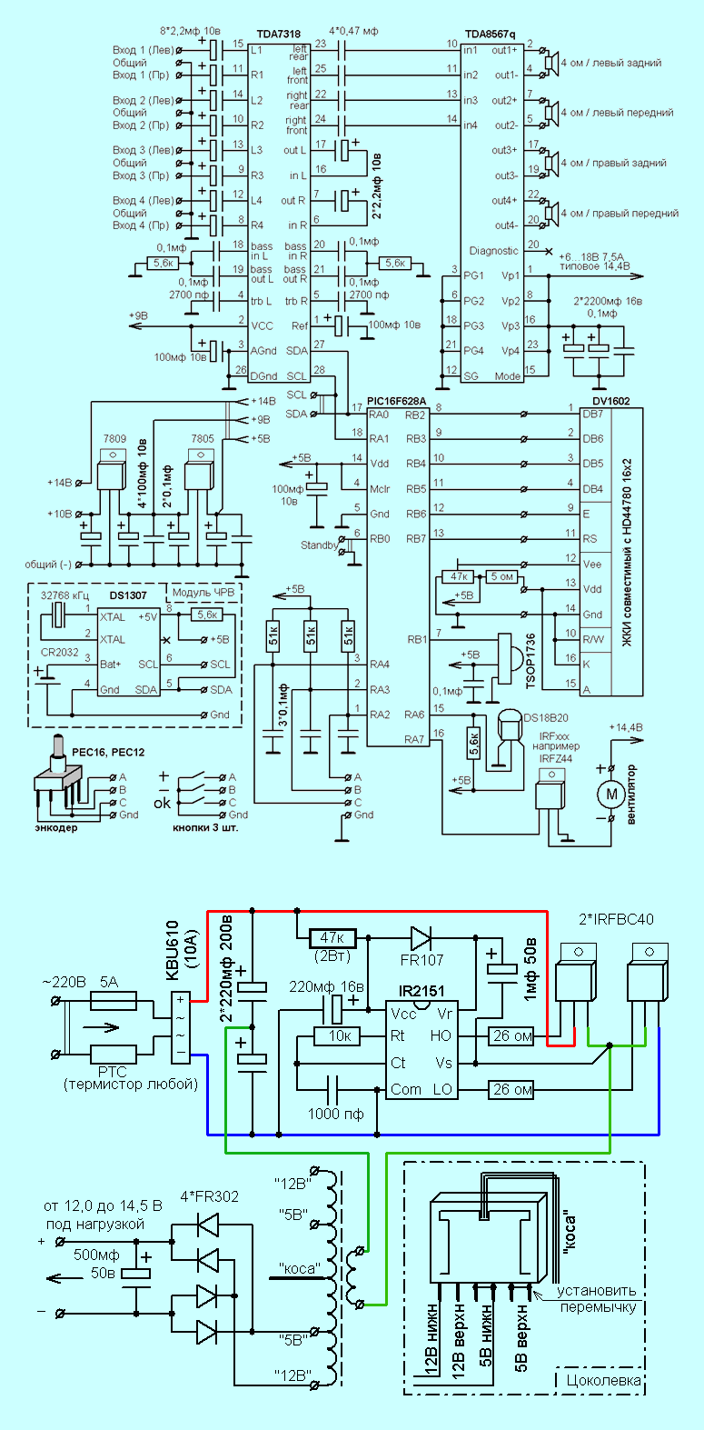
The heart of our amplifier is the PIC16F628A microcontroller. The microcontroller controls the TDA7318 sound processor. This wonderful microcircuit performs all the above functions for sound processing, we will consider its capabilities a little later. The TDA8568q was chosen as the power amplifier. This is a four channel car power amplifier with 25W per channel. Next, we will show how to increase the output power.
Of course, in addition to all of the above, our amplifier is not deprived of control, display, temperature monitoring, cooling control, standby mode functions, it also has a clock and calendar function.
The amplifier can be controlled manually with buttons or the encoder, as well as remotely using the remote control. There are two firmware options to choose from: you can use the firmware adapted for the use of the buttons (when there is no encoder) and you can also use the firmware adapted for the use of the encoder. Otherwise, the functionality of the firmware does not differ from each other.
The amplifier can also be controlled using an IR remote, which should operate to the RC-5 standard; many remote controls from household appliances work in this standard (eg LG, Philips, etc.). It should be noted that the firmware also supports remote controls working in the inverted RC-5 standard.
Surround Sound Control Circuit

Screen saver in run mode – turns on if user has been on for 10 seconds. does not make any adjustments. In this screen saver we see the current time and the current temperature.
Screen saver in standby mode ( Standby ) – mode is entered from both the remote control and the encoder/buttons. This is the power button on the remote. If you want to enter this mode from the encoder / buttons, you must press and hold for 4-5 seconds. The encoder button or the “OK” button was pressed. The same is done to exit this mode.
It should be noted that the operation of the Wait line shown in the diagram is directly related to the standby mode, if we see the “Waiting” screensaver, the signal level of the line is low, in all other cases the signal level of the line is high.
SILENT mode can only be selected with the remote control. We believe that muting the volume with manual control is much easier than going into a special mode and suddenly turning the volume off.
Setting the time and date. When you enter this mode, you will be prompted to accept or reject (yes / no) to set the time and date values. If you accept, the digits of the date and time and the more / less buttons are repeated to set the required values.
In the absence of an RTC module, a 5.6 kΩ pull-up resistor must be soldered to the board between the SDA and +5V lines. For ease of installation, an additional hole in the motherboard is provided at the installation site of the RTC module (see figure below). If this resistor is not adjusted, the clock will not display the correct time. If there is a pull-up resistor but no RTC module (or DS1307 chip in the module), the microcontroller blocks the output of the clock function.
temperature setting. In the photo above, we see the current temperature (38.9) in the top row. It changes dynamically, so one human breath is enough to see the change. Bottom line, we set the threshold (from the remote or encoder/buttons) at which the fan will operate in the positive temperature range from 0 to 99 degrees. In our example, the fan will run if the current temperature rises above 40.0 degrees. The fan start algorithm includes “child protection”, that is, the fan will work in any case if the temperature threshold exceeds 75 degrees.
In the absence of the DS18B20 sensor, the temperature display will show 00.0. Accordingly, the fan will always be off.
Firmware version – displayed on the screen after entering the number string “1978” from the remote control.
SMPS CIRCUIT
The input is equipped with a PTC thermistor (Positive Temperature Coefficient) – a semiconductor resistor with a positive temperature coefficient that sharply increases its resistance when a certain characteristic temperature TRef is exceeded. Protects power switches at turn-on while charging capacitors. Diode bridge at the input to rectify the mains voltage to a current of 10A. The diode assembly type “vertical” is used, but you can use the diode assembly type “stool”.
A pair of capacitors at the input is taken at a rate of 1 microfarad per 1 watt. In our case, the capacitors will “pull” the 220W load. Quenching resistor in the power supply circuit of the drive with a power of 2 W. MLT-2 type domestic resistors are preferred.
Driver IR2151 – For controlling the gates of field effect transistors operating under voltage up to 600V. Possible replacement for IR2152, IR2153. If the name contains the index “D”, for example IR2153D, the diode FR107 in the driver harness is not needed. The driver alternately opens the gates of the field effect transistor defects with a frequency set by the elements in the Rt and Ct legs.
Field effect transistors are preferably used by IR (International Rectifier). Choose with a voltage of at least 400 V and minimum resistance in the on state. The lower the resistance, the lower the heat and the higher the efficiency. IRF740, IRF840 etc. you can recommend. The IR FET Handbook can be downloaded here. Attention! Do not short-circuit the flanges of field-effect transistors; When mounting on a radiator, use insulating gaskets and bushing washers .
A typical step-down transformer from a computer power supply. As a rule, the wiring diagram corresponds to that shown in the diagram. Homemade transformers wound on ferrite tori also work in this circuit. Calculation of homemade transformers is carried out at a conversion frequency of 100 kHz and at half the rectified voltage (310/2 = 155V).
Diodes with a recovery time of not more than 100 ns at the output. Diodes from the HER (High Efficiency Rectifier) family meet these requirements. Not to be confused with Schottky diodes.
Source: qrz.ru Surround Sound System schematic pcb code files alternative link:


100W Hi-fi AmplifierCircuit symasym
Quality design a beautiful Amplifier circuit have all the details oscilloscopes and voltage measurements PCBs have specified additional circuit diagrams
100W HI-FI Amplifier
THD: ~0.005% (measured) sim’d: 0.002%
Power into 8ohm: 60 watts
Power into 4ohm: 100 watts
Gain: 32dB (~1:40) full output at 0.7v input (0.5v rms)
Feedback: 57dB
Phase margin: > 90°
Supply voltage: +/- 36v
Biasing: 55ma, 12.1mv across a single 0.22 ohm
Frequency response: 3.2hz to 145khz (-1db) using 4.7uf input cap
Phaseshift at 10khz: <3° More will follow !